
2M communication detection method and detection device

A detection device and communication detection technology, which is applied in the field of non-loop 2M data communication detection, can solve the problems of high load of communication lines, reduce the communication speed at both ends of the communication circuit, etc., and achieve the effect of reducing the reduction of communication speed

Active Publication Date: 2017-11-24
STATE GRID FUJIAN ELECTRIC POWER CO LTD
View PDF7 Cites 3 Cited by
  • Summary
  • Abstract
  • Description
  • Claims
  • Application Information

AI Technical Summary

Problems solved by technology

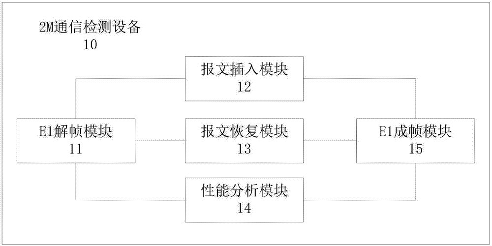
[0008] For this reason, it is necessary to provide a 2M communication detection method and 2M communication detection equipment, which are used to solve the problem that when the detection equipment detects the communication circuit, the communication line load is too high and the communication speed at both ends of the communication circuit is reduced.

Method used


Image

  • 2M communication detection method and detection device
  • 2M communication detection method and detection device

Examples


Embodiment Construction

[0039] In order to explain in detail the technical content, structural features, achieved goals and effects of the technical solution, the following will be described in detail in conjunction with specific embodiments and accompanying drawings. In the following description, for purposes of explanation, numerous specific details are set forth in order to provide a thorough understanding of one or more aspects. It may be evident, however, that such aspects may be practiced without these specific details.

[0040] see figure 1 , is the detection equipment connection diagram, the detection equipment A and the detection equipment B are connected in series on both sides of the path to be tested. It can be understood that the figure is only for the convenience of representation, and the path to be tested is actually a communication line. The inventor provides a 2M communication detection method comprising the following steps:

[0041] S101. The detection device A receives the data ...


PUM


Abstract

The invention provides a 2M communication detection method and detection device and is used for solving the problem that when the detection device detects a communication circuit, the excessive communication line load is liable to cause and the communication speed at two ends of the communication circuit is liable to reduce. The method and device relate to 2M data channel detection, particularly relate to non-loop 2M data channel detection. The method comprises the steps of S101, receiving data D by the detection device A and analyzing the data D, wherein the data D is E1 frame data; S102, inserting self-defined link protocol message data into an SA field of the data D, wherein the self-defined link protocol message data comprises a mark of the detection device A, and time information of receiving the data D by the detection device A; S103, packaging the data D into E1 frames and sending the E1 frames; and S104, receiving the data D by the detection device B and analyzing the received data D. The detection device can be connected with the communication circuit for a long time.

Description

technical field [0001] The invention relates to 2M data channel detection, in particular to non-loop 2M data communication detection. Background technique [0002] Digital transmission analyzer is the most powerful and reliable tool for daily maintenance work of telecom engineers and technicians. Currently, it supports conventional 2M and data channel bit error test functions, as well as test and analysis functions for 2M frame structure data, dual-channel E1 monitoring, loop delay, switching delay, output waveform, output jitter, and signal level. [0003] However, the cause of the failure of the data channel in reality is complicated, and the existing analyzer cannot test such as the transmission problem between two points on the path, so that the location of the faulty device or line cannot be determined. [0004] The 30-channel pulse code modulation PCM in Europe is referred to as E1, and the rate is 2M / s. A time-division multiplexing frame of E1 (its length T=125us) is...

Claims


Application Information

Patent Timeline
Patent Type & Authority Applications(China)
IPC IPC(8): H04L12/26H04L12/24H04L1/00
CPCH04L1/004H04L1/0063H04L1/0083H04L41/06H04L43/08H04L43/0823H04L43/0852H04L43/50
Inventor 吴文宣刘永清连纪文李宏发陈端云叶勇周晓东邱丽霓徐杰钱思源林旭升葛元鹏林屹林琳郑蔚涛涂林峰何尚骏侯功华
Owner STATE GRID FUJIAN ELECTRIC POWER CO LTD
Learn More