
Adjustable pump valve self-locking antiskid differential

An anti-skid differential, adjustable technology, applied in the direction of differential transmission, belt/chain/gear, mechanical equipment, etc., can solve the problems of complex structure and shape of parts, easy wear of friction contact parts, insufficient power distribution, etc.

Pending Publication Date: 2017-11-24
熊然
View PDF5 Cites 0 Cited by
  • Summary
  • Abstract
  • Description
  • Claims
  • Application Information

AI Technical Summary

Problems solved by technology

[0002] The conventional cross-shaft differential used in ordinary vehicles has an obvious defect of "differential speed without torque" in its design and structural principle, that is, when one side of the driving wheel slips and spins, the other side of the driving wheel Loss of power, causing the vehicle to bog down
In order to overcome this defect, various improvements have been made to the differential, and various anti-skid locking mechanisms have been installed. At present, there are mainly friction plate locking methods, worm gear locking methods, and viscous coupling locking methods. , but there are still the following disadvantages: the structure and parts are complex in shape, the production and maintenance costs are high, some actions and responses are slow, the trigger speed difference is difficult to adjust, or after the load is too large, the friction contact parts are easy to wear, slip, and power distribution Insufficient, resulting in unsatisfactory range of adaptation and cost of use

Method used


Image

  • Adjustable pump valve self-locking antiskid differential
  • Adjustable pump valve self-locking antiskid differential
  • Adjustable pump valve self-locking antiskid differential

Examples


Embodiment Construction

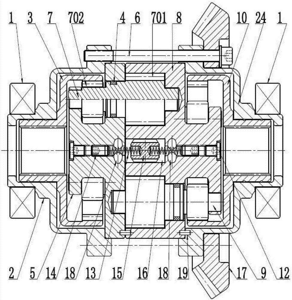
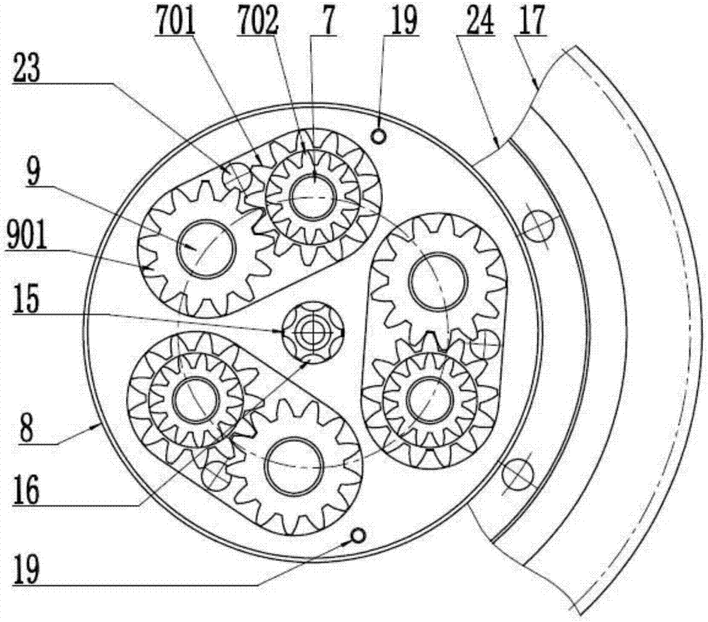
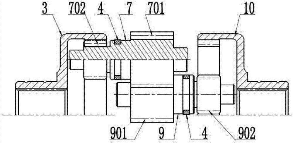
[0029] See attached Figure 1-3 , which shows one of the preferred and preferred structures of the adjustable pump-valve self-locking anti-slip differential involved in the present invention, which mainly consists of differential left case 2, differential right case 24, three groups A gear pump, a group of flow limiting valves, a left half-shaft ring gear 3, and a right half-shaft ring gear 10 are formed.

[0030] The pump body 8 of the above-mentioned three groups of gear pumps, the pump cover 5, the left and right shells 2, 24 of the differential, and the external large gear 17 are fastened by screws 6 and positioning pins 19, and are rotatably supported by the bearing 1; the above-mentioned three groups of gears pump, each group has a left drive gear shaft 7 and a right drive gear shaft 9; the left drive gear shaft 7 contains a left pump oil gear 701 and a left drive gear 702; the above right drive gear shaft 9 contains a right pump oil gear 901 and the right drive gear 90...


PUM


Abstract

The invention provides an adjustable pump valve self-locking antiskid differential which is mainly composed of a differential shell, a gear pump, a bidirectional throttling valve and left and right semi-shaft gear rings. Two gear shafts of the gear pump respectively extend out of a driving gear lefttwards and rightwards to be meshed with the left and right semi-shaft gear rings of wheel semi-shafts; rotating speed difference of the left and right semi-shaft gear rings relative to the gear pump drives a gear shaft of the gear pump to automatically rotate to pump oil; when oil flow exceeds flow allowed to pass and set by the throttling valve, the throttling valve automatically closes and locks the gear shaft of the gear pump to disable continuous rotating so as to lock the left and right semi-shaft gear rings to rotate synchronously with the gear pump to stop a wheel on one side from sliding and idling and to drive a trapped wheel. By the adjustable pump valve self-locking antiskid differential, when the wheel on one side slides and idles, the left and right wheel semi-shafts can be quickly and automatically locked to synchronous running and can be automatically unlocked after a vehicle travels normally. The adjustable pump valve self-locking antiskid differential has the advantages of simple structure, low manufacturing and maintaining cost, adjustability in speed difference for triggering locking and large output torque.

Description

technical field [0001] The invention relates to a differential, in particular to an adjustable differential which can be automatically locked to prevent wheel slipping and can be automatically unlocked. Background technique [0002] The conventional cross-shaft differential used in ordinary vehicles has an obvious defect of "differential speed without torque" in its design and structural principle, that is, when one side of the driving wheel slips and spins, the other side of the driving wheel The lack of power resulted in the vehicle bogging down. In order to overcome this defect, various improvements have been made to the differential, and various anti-skid locking mechanisms have been installed. At present, there are mainly friction plate locking methods, worm gear locking methods, and viscous coupling locking methods. , but there are still the following disadvantages: the structure and parts are complex in shape, the production and maintenance costs are high, some actio...

Claims


Application Information

Patent Timeline
Patent Type & Authority Applications(China)
IPC IPC(8): F16H48/27F16H48/12
CPCF16H48/12F16H48/27
Inventor 熊然
Owner 熊然
Learn More