
Supporting base structure

A technology of support seat and support frame, applied in mechanical equipment, fixtures, etc., can solve the problems of poor mechanical strength, damage, easy deformation, etc.

Pending Publication Date: 2017-11-24
MANTALL HEAVY IND
View PDF0 Cites 0 Cited by
  • Summary
  • Abstract
  • Description
  • Claims
  • Application Information

AI Technical Summary

Problems solved by technology

[0003] Both sides of the support seat need to be fixed with bolts or gas fixtures; the stress concentration around the fixing hole of the support seat is easily deformed or damaged; the mechanical strength is poor, and the support seat needs to be thickened to meet the mechanical strength requirements

Method used


Image

  • Supporting base structure
  • Supporting base structure
  • Supporting base structure

Examples


Embodiment 1

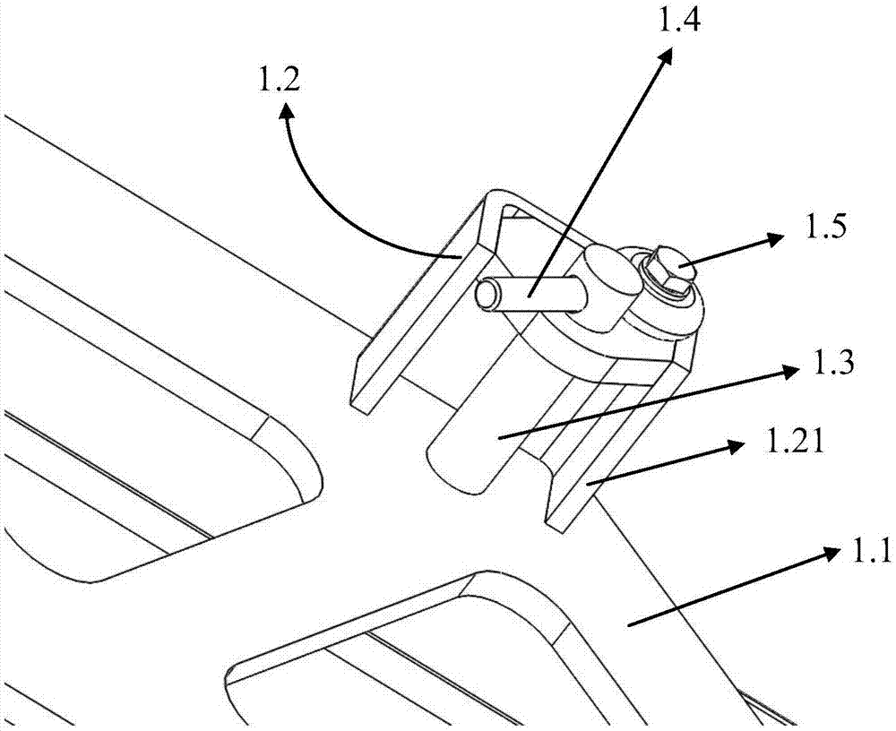
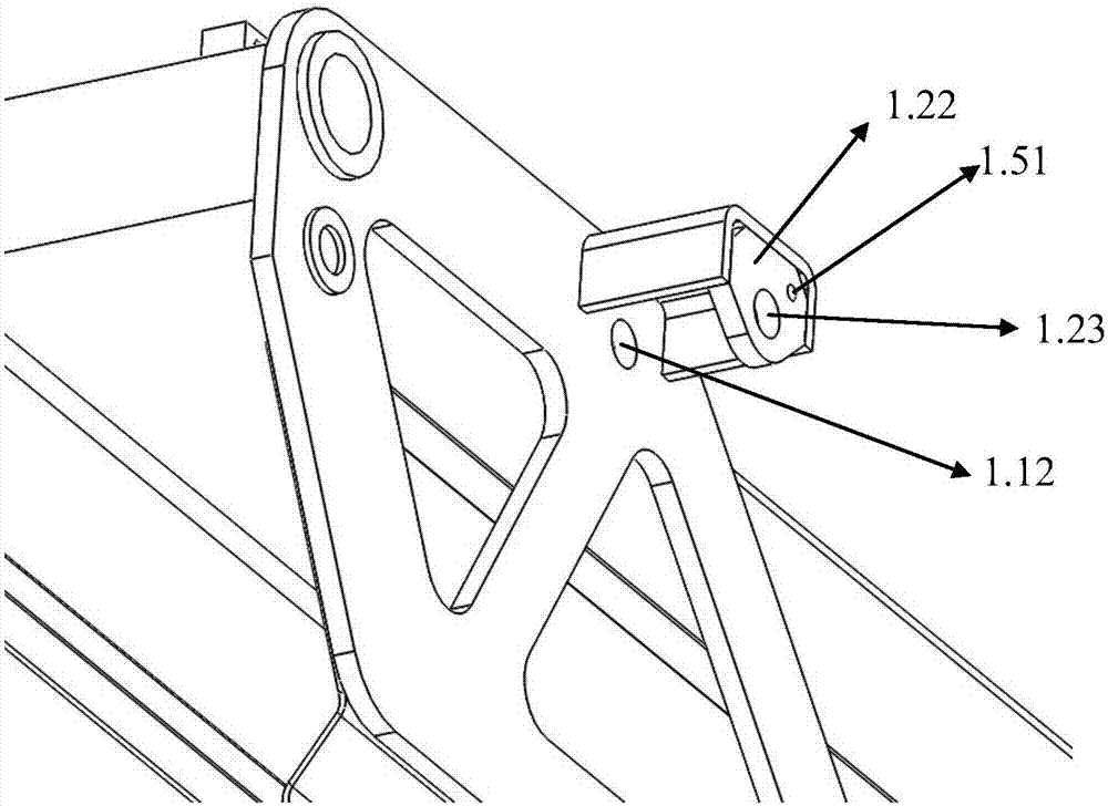
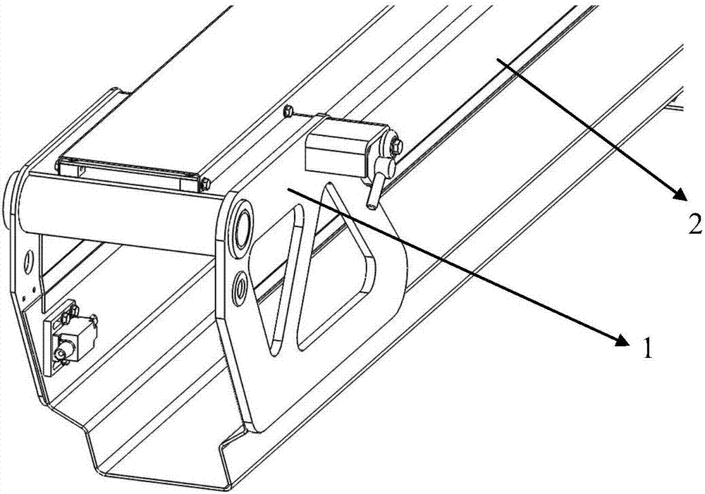
[0018] As shown in the figure, a supporting base structure 1 is used to fix the to-be-connected mechanism 2 on the supporting base structure 1. It includes a support frame 1.1 and a fixing seat 1.2 arranged on one side of the support frame. The support frame 1.1 includes at least a fixed side wall 1.11, and the fixed side wall has a through fixing hole 1.12; the fixing seat 1.2 has a connecting portion 1.21 and a limit plate 1.22 , The connecting portion 1.21 has three connecting surfaces, all of which are connected to the fixed side wall 1.11 and the limit plate 1.22. The limit plate 1.22 has a through fixing hole 1.23, and the fixing hole 2.1 on the connecting mechanism 2 is to be fixed. The fixing holes 1.12 on the side wall and the fixing holes 1.23 on the limiting plate are distributed in a straight line, and the fixing shaft 1.3 is inserted into the three fixing holes for fixing.

[0019] The fixed shaft 1.3 has a limit hole that allows the limit shaft 1.4 to pass through, ...


PUM


Abstract

The invention discloses a supporting base structure which at least covers the surface of a to-be-connected mechanism partially. The to-be-connected mechanism is provided with a fixing hole used for fixing. The supporting base structure comprises a supporting frame and a fixing base arranged on one side of the supporting frame. The supporting frame at least comprises a fixing side wall which is provided with a through fixing hole. The fixing base is provided with a connecting portion and a limiting plate. One end of the connecting portion is fixed to the supporting frame, and the other end of the connecting portion is connected with the limiting plate. The limiting plate is provided with a through fixing hole. The fixing hole in the to-be-connected mechanism, the fixing hole in the fixing side wall and the fixing hole in the limiting plate are distributed in the manner of forming one straight line. A fixing shaft is inserted into the three fixing holes to be fixed.

Description

Technical field [0001] The invention relates to a supporting seat structure. Background technique [0002] The support base is an important fixed connection structure. In the existing support base structure, perforations are generally used in the mechanism to be connected and the support base, and the through bolts or pins are used for fixing. This fixing method has the following disadvantages: [0003] Both sides of the support base need fixing bolts or gas fixing parts; the stress concentration around the support base fixing hole is easy to be deformed or damaged; the mechanical strength is poor, and the support base needs to be thickened to meet the mechanical strength requirements. Summary of the invention [0004] In order to solve the problems existing in the prior art, the present invention designs a supporting seat structure, which has a simple structure and a reasonable design, effectively disperses stress, and meets the requirements of rigid fixation. [0005] In order to ...

Claims


Application Information

Patent Timeline
IPC IPC(8): F16B1/02
CPCF16B1/02
Inventor 沈李陈赛健
Owner MANTALL HEAVY IND
Learn More