
Gap distribution-type auxiliary weir structure

A two-way dam and diversion-type technology, which is applied in sea area engineering, construction, barrage/weir, etc., can solve the problems of increased cost of downstream reservoir banks, scrubbing of downstream reservoir banks near the dam, and no significant effect of water flow over the dam. , to achieve the effect of reducing erosion, weakening erosion, and reducing water flow energy

Pending Publication Date: 2017-11-24
POWERCHINA CHENGDU ENG
View PDF6 Cites 2 Cited by
  • Summary
  • Abstract
  • Description
  • Claims
  • Application Information

AI Technical Summary

Problems solved by technology

[0006] The invention provides a notch diversion type two-way dam structure, which solves the problem that the existing two-way dam structure has no significant effect on the improvement of the flow state of the water flow passing through the dam, and it is easy to form a folding and flushing water flow, which will cause erosion of the bank near the downstream of the dam; and The water flow across the dam continues to scour the downstream apron and riverbed, resulting in a significant increase in the cost of downstream bank support

Method used


Image

  • Gap distribution-type auxiliary weir structure
  • Gap distribution-type auxiliary weir structure
  • Gap distribution-type auxiliary weir structure

Examples


Embodiment Construction

[0023] The present invention will be further described below in conjunction with accompanying drawing.

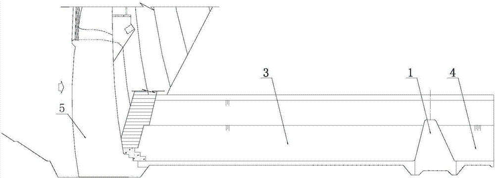
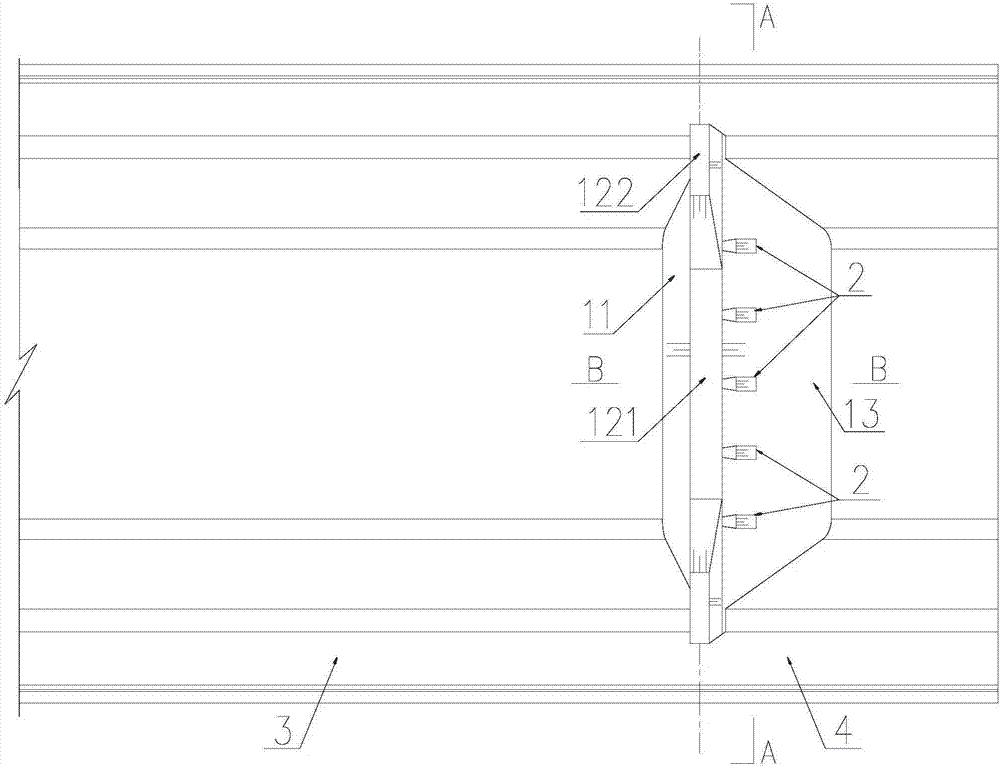
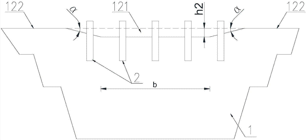
[0024] Such as Figure 2-5 As shown, the gap shunt type secondary dam structure of the present invention, the secondary dam 1 is a gravity dam, the secondary dam 1 includes an upstream dam surface 11, a dam top surface 12 and a downstream dam surface 13, and the upstream dam surface 11 faces the pond water 3 . A notch 121 is set in the middle of the dam crest 12, and the two sides of the notch 121 are respectively side dam sections 122; the notch 121 of the dam crest 12 is close to the downstream dam face 13, or the gap 121 on the top of the downstream dam face 13 is arranged at intervals with diverter piers 2 .

[0025] Such as Figure 2~3 As shown, the width b of the notch 121 does not exceed the width of the river bed, and both ends of the notch 121 are respectively connected to the side dam section 122 through slopes. The gap 121 lowers the elevation of the dam top ...


PUM


Abstract

The invention discloses a gap distribution-type auxiliary weir structure and relates to the technical field of hydraulic structure design. The problem that weir-passing waterflow of an existing auxiliary weir easily forms deflected scour flow, accordingly a close-weir downstream reservoir bank is soured, the weir-passing waterflow continuously sours downstream apron and a riverbed, and the cost for supporting the downstream reservoir bank is remarkably increased is solved. According to the adopted technical scheme, the gap distribution-type auxiliary weir structure is a gravity weir, a gap is formed in the middle of the top face of the weir, falling of downward discharged waterflow at the auxiliary weir is decreased, and scouring to a riverbed base plate and the reservoir bank is weakened. The gap formed in the top face of the weir is close to a downstream weir face, or distributing piers are arranged at the gap formed in the top of the downstream weir face at intervals, so that the distributed weir-passing waterflow is discharged in an approximate and uniform distribution mode in a centralized form, the possibility of backflow and deflected scour flow is reduced, the waterflow passing through the weir smoothly and stably returns back to a tank, and the scouting to the reservoir bank is reduced. A continuous pressing slope body is arranged at the top of an upstream weir face, and the waterflow in a plunge pool is prevented from flowing across the top face of the weir, so that the energy dissipation of the waterflow is full.

Description

technical field [0001] The invention relates to the technical field of design of hydraulic structures, in particular to a gap-splitting secondary dam structure of a hydraulic energy dissipation structure. Background technique [0002] In recent years, with the country's increasing requirements for green and clean energy and environmental protection in engineering construction, water conservancy and hydropower engineering construction has gradually shifted from a technology-fund-constrained type to an environment-constrained type. How to minimize the impact on the ecological environment during the project construction period has become a special concern of the project construction unit and relevant river basin organizations. In water conservancy and hydropower projects, the impact of the discharge of water from the reservoir area on the riverbed and reservoir bank is a common environmental problem in hydropower projects. [0003] Under the existing technical conditions, in o...

Claims


Application Information

Patent Timeline
IPC IPC(8): E02B8/06
CPCE02B8/06
Inventor 李金洋张冲张敬刘小强
Owner POWERCHINA CHENGDU ENG
Learn More