
Two-way convection graded drop energy dissipation shaft

A drop-type, vertical shaft technology, which is applied in sea area engineering, construction, barrage/weir, etc., can solve the problems of excessive flow velocity, large difference in water surface inside and outside the flow, and low space utilization, so as to reduce the water level and flow velocity, The structure is compact and the energy dissipation effect is improved

Inactive Publication Date: 2019-05-10
HOHAI UNIV +1
View PDF4 Cites 0 Cited by
  • Summary
  • Abstract
  • Description
  • Claims
  • Application Information

AI Technical Summary

Problems solved by technology

The existing deep tunnel system inflow shafts include direct drop type, rotating slide type, rotating ladder type and folded plate drop type, etc. When the drop depth is large, the water flow velocity is too large for the direct drop type shaft, which is usually not suitable for use; The difference between the inside and outside of the water flow in the slideway shaft and the rotary ladder shaft rotary channel is relatively large, which significantly affects the discharge flow of the shaft, and the energy dissipation effect of the rotary slideway shaft is usually not good; Under these conditions, the energy dissipation effect of water flow and anti-cavitation cavitation effect are relatively good, and it has good adaptability to large-depth shaft drops, but the proportion of shaft flow passages is usually small. Under the same discharge flow conditions, A larger shaft diameter is required, and the space utilization rate is low
At present, there is no national standard for the structural layout of the inflow shaft of the storage tunnel system. Design a shaft form with a simple structure, strong adaptability to inflow flow and drop depth, and can meet the requirements of inflow, energy dissipation and exhaust at the same time. It is of great significance to the safe and stable operation of the storage tunnel system engineering

Method used


Image

  • Two-way convection graded drop energy dissipation shaft
  • Two-way convection graded drop energy dissipation shaft
  • Two-way convection graded drop energy dissipation shaft

Examples


Embodiment

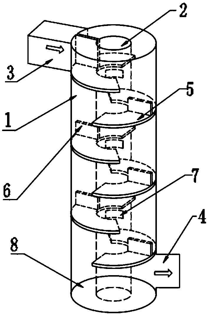
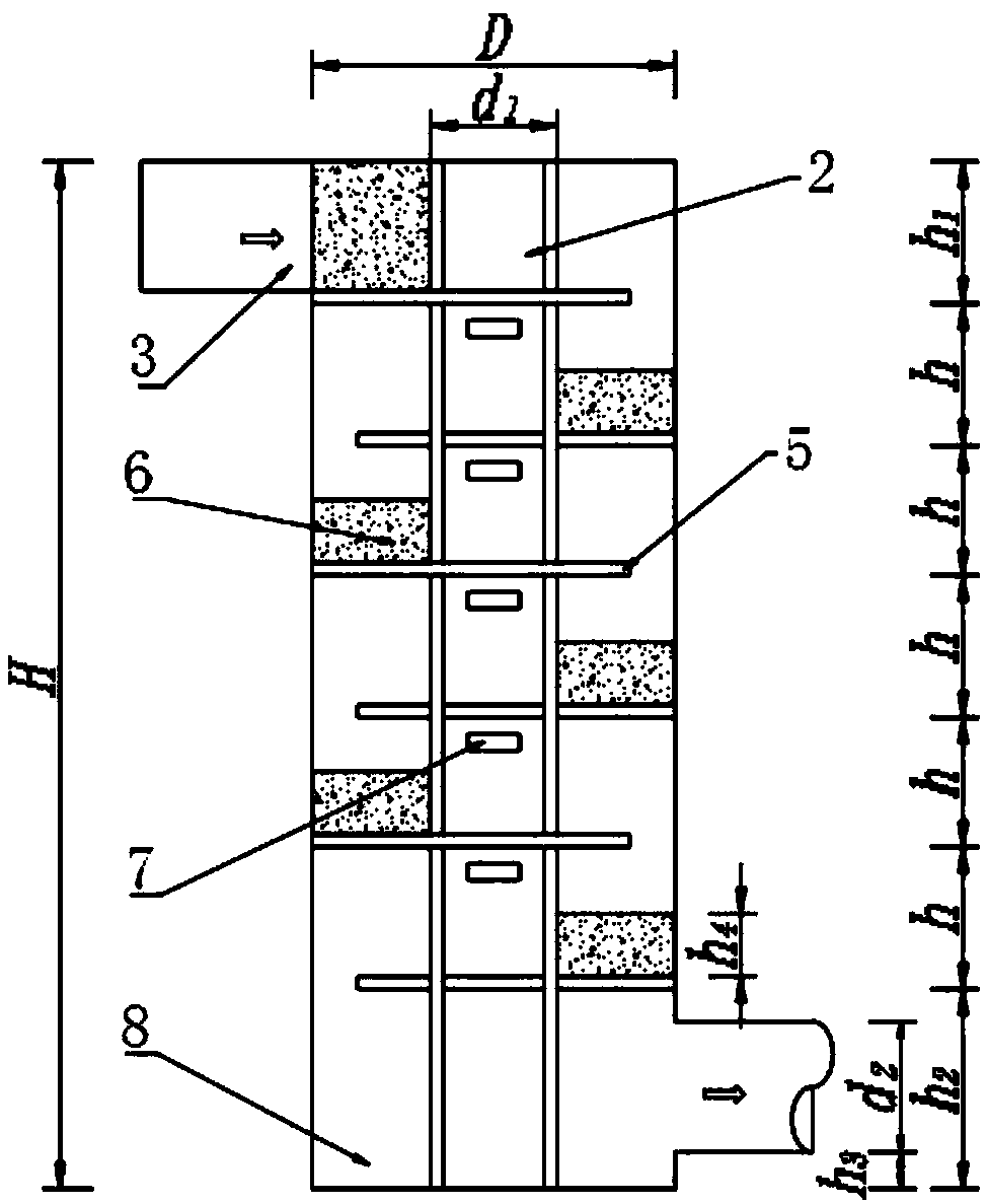
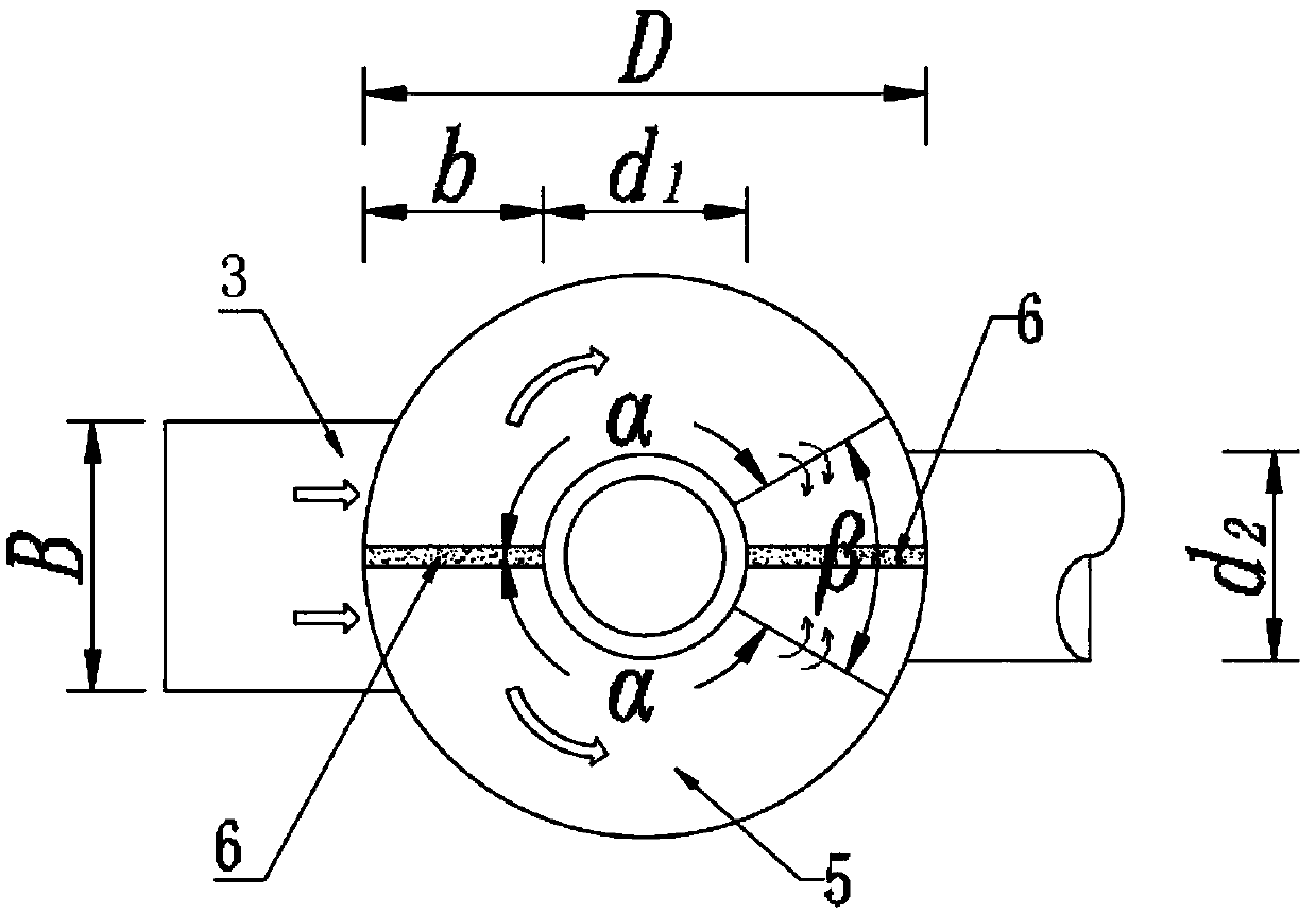
[0029] In the embodiment, the structural arrangement of the two-way convection graded drop-type energy dissipation shaft is as follows: figure 1 , figure 2 , image 3 As shown, the two-way convection graded drop energy dissipation shaft includes a shaft 1, an exhaust pipe 2, a water inlet 3, a storage tunnel access port 4, a drop plate 5, a diverter plate 6, a ventilation hole 7 and a water cushion 8. Among them, the number of drop plates 4 is 6. The drop plate 5 and the diverter plate 6 on the first floor are respectively connected with the water inlet channel 3, and the elevation of the drop plate 5 on the bottom floor is higher than the elevation of the top of the entrance 4 of the regulation and storage tunnel. The height of the top of the first-layer diverter plate 6 is flush with the top elevation of the shaft 1 , and the height of the remaining diverter plates 6 is lower than the distance between the adjacent upper and lower layers of the drop plates 5 . The exhaust...


PUM


Abstract

The invention discloses a bilateral flow graded falling type energy dissipation vertical shaft. The bilateral flow graded falling type energy dissipation vertical shaft comprises a vertical shaft and an exhaust pipe which are concentrically arranged in a sleeving manner; an annular zone is formed between the inner wall of the vertical shaft and the outer wall of the exhaust pipe; the upper end of the annular zone is connected with a water inlet channel; the lower end of the annular zone is connected with a regulation and storage tunnel access port; a plurality of falling plates are arranged in the annular zone from top to bottom in a staggered manner at equal intervals; and splitter plates used for symmetrically dividing the falling plates to form bilateral flow are vertically arranged on the falling plates. According to the bilateral flow graded falling type energy dissipation vertical shaft, multiple grades of falling plates are arranged in the vertical shaft, flow velocity of discharged water is decreased under opposite rushing action and aerification action of falling bilateral flow and turbulent diffusion action of water cushion layers on the falling plates, and cavitation and erosion of local regions of the vertical shaft are effectively inhibited while the energy dissipation effect of the vertical shaft is improved; and the splitter plates divide waterflow into half, flow in a unit flowing channel is greatly reduced, water level on the falling plates is lowered, flow velocity on the falling plates is decreased, and the energy dissipation effect of the vertical shaft is improved.

Description

technical field [0001] The invention relates to the technical field of drainage engineering, in particular to a two-way convection graded drop-type energy dissipation shaft. Background technique [0002] The inflow shaft in the regulation and storage tunnel system of municipal engineering usually needs to adapt to the requirements of different inflow flow and water drop depth according to the characteristics of the pipeline arrangement. The existing deep tunnel system inflow shafts include direct drop type, rotary slide type, rotary stepped type and folding plate drop type, etc. When the drop depth is large, the water flow velocity of the direct drop shaft is too large, which is usually not suitable for use; The difference between the inner and outer water surface of the water flow in the rotary channel of the slide shaft and the rotary stepped shaft is large, which significantly affects the discharge flow of the shaft, and the energy dissipation effect of the rotary slide s...

Claims


Application Information

Patent Timeline
Patent Type & Authority Patents(China)
IPC IPC(8): E02B8/06
CPCE02B8/06
Inventor 陈毓陵叶源新王晓升顾贇周春天冯建刚张睿王碧波王树仿孙靖康
Owner HOHAI UNIV
Learn More