
Respiratory heat dissipation structure for hub motor

A technology of heat dissipation structure and in-wheel motor, applied in the direction of hub, wheel, transportation and packaging, etc., can solve the problems of high manufacturing cost, difficult maintenance, complicated structure of oil-cooled in-wheel motor, etc. Effects of thermal expansion damaging the motor

Active Publication Date: 2017-11-24
NEW ANANDA DRIVE TECHN SHANGHAI
View PDF4 Cites 4 Cited by
  • Summary
  • Abstract
  • Description
  • Claims
  • Application Information

AI Technical Summary

Problems solved by technology

However, the oil-cooled hub motor provided by this patent document has a complex structure, high manufacturing cost, and if damaged, it is very difficult to repair

Method used


Image

  • Respiratory heat dissipation structure for hub motor
  • Respiratory heat dissipation structure for hub motor
  • Respiratory heat dissipation structure for hub motor

Examples


Embodiment Construction

[0051] The present invention will be described in detail below in conjunction with specific embodiments. The following examples will help those skilled in the art to further understand the present invention, but do not limit the present invention in any form. It should be noted that those skilled in the art can make several modifications and improvements without departing from the concept of the present invention. These all belong to the protection scope of the present invention.

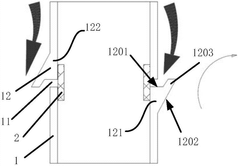
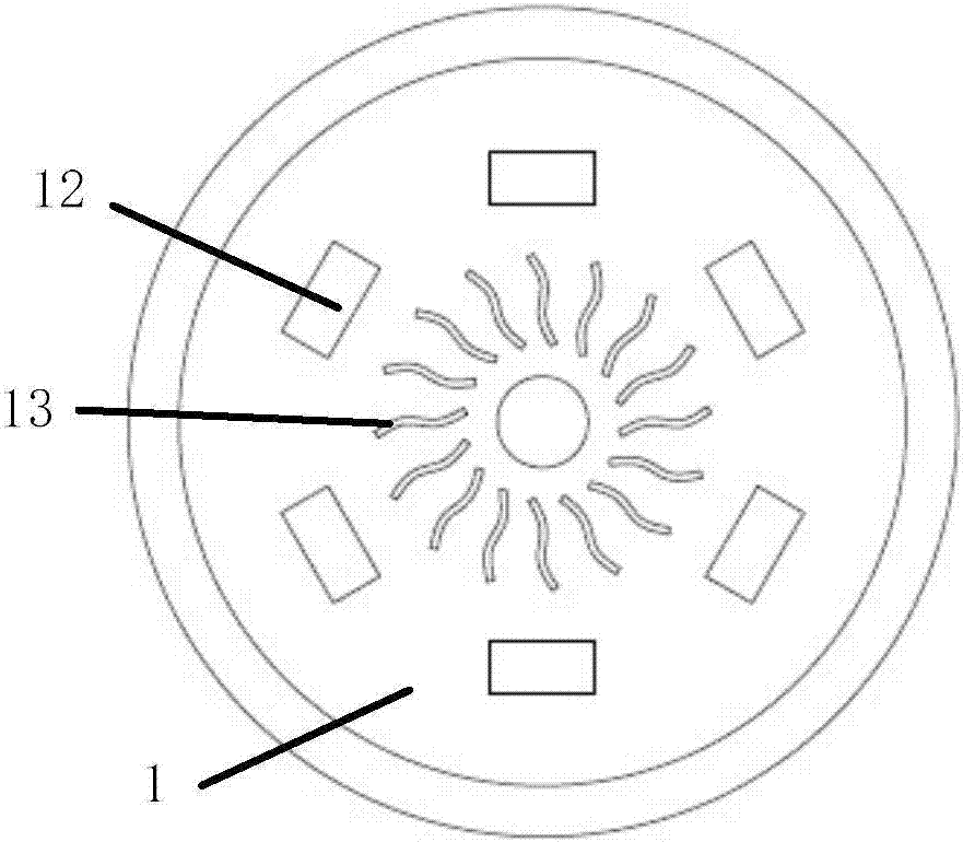
[0052] Such as figure 1 , image 3 As shown, in the embodiment, the hub 1 motor breathing heat dissipation structure provided by the present invention includes the hub 1 and the waterproof and breathable membrane assembly 2, wherein the hub 1 is provided with a breathing hole 11 and a raised portion, and the raised portion includes a guide protrusion 12. The waterproof and breathable membrane assembly 2 is arranged in the hub 1 and covers the radial cross-section of the breathing hole 11 to ensur...


PUM


Abstract

The invention provides a respiratory heat dissipation structure for a hub motor. The respiratory heat dissipation structure for the hub motor comprises a hub and a waterproof breathable film component; a breathing hole and projection parts are arranged on the hub; the waterproof breathable film component is arranged within or outside the hub or within the breathing hole; the waterproof breathable film component covers a radial cross section of the breathing hole; the projection parts are arranged on the external side surface of the hub; the projection parts comprise flow guide projections; and the flow guide projections correspond to the breathing hole. According to the respiratory heat dissipation structure for the hub motor, as the flow guide projections are arranged on the external surface of the hub, a pressure difference is formed between two sides of the breathing hole so as to drive hot air within the hub to flow out; therefore, the performance of the hub motor can be furthest developed; in addition, parts within the breathing hole can also be protected to achieve double benefits.

Description

technical field [0001] The invention relates to the field of electric vehicle accessories, in particular to a hub motor breathing and cooling structure. Background technique [0002] In the prior art, the in-wheel motor of an electric vehicle has relatively high requirements for waterproofing because it is used outdoors, and the motor is required to operate normally when it is immersed in water. This requires the motor to be completely sealed. However, the motor will generate heat when it is in use. After the heat is generated, the air inside the motor will expand. When the expansion pressure reaches a certain level, the air will overflow from the rubber sealing ring, etc. When the motor is stopped, the entire motor will cool down, and the inside of the motor will Negative pressure is generated, and external air will enter the inside of the motor. If the outside is a relatively humid environment or soaked in water, water will be sucked into the inside of the motor, causing ...

Claims


Application Information

Patent Timeline
Patent Type & Authority Applications(China)
IPC IPC(8): B60B27/00
CPCB60B27/0015B60B27/0047B60B2900/321B60B2900/111B60B2900/5114B60B2900/513Y02T10/64
Inventor 黄洪岳徐建卓达夏业中
Owner NEW ANANDA DRIVE TECHN SHANGHAI
Learn More