Magnetic control wheel based on electromagnetic propulsion system

An electromagnetic propulsion and magnetic control technology, applied in the field of vehicles, can solve the problems of inability to drive the wheels, bumpy vehicles, high fuel consumption, etc., and achieve the effects of convenient reverse rotation, improved shock absorption performance, and fast running speed.

Active Publication Date: 2017-11-21
XUZHOU XUANKE AGRI MASCH CO LTD
View PDF6 Cites 4 Cited by
  • Summary
  • Abstract
  • Description
  • Claims
  • Application Information

AI Technical Summary

Problems solved by technology

The wheel in the existing structure is usually composed of a wheel shaft, a wheel hub, a rim, and a tire. The outer circumference of the wheel hub usually uses a rubber tire and keeps it inflated by means of inflation. Once the inflation is insufficient or deflated, the wheel will not be able to drive. When driving on the road surface, the potholes will cause the vehicle to bump, and the cushioning performance of the wheels themselves is extremely poor, so an additional shock absorption system is required
Existing wheels, especially in automotive applications, are usually driven by the vehicle's drive system to drive the wheel shaft to rotate, and the wheel is driven to rotate to realize the driving of the vehicle, and gasoline and diesel fuel are burned in the engine to generate propulsion through the transmission mechanism to drive the wheel shaft to rotate, and the structure is complex , and the fuel consumption is high, not only the vehicle structure is complex, the cost is high, but also the fuel consumption is serious, the vehicle speed is low, the wheel hub and the wheel shaft are severely worn, and the driving method of the wheel cannot be simplified

Method used


Image

  • Magnetic control wheel based on electromagnetic propulsion system
  • Magnetic control wheel based on electromagnetic propulsion system
  • Magnetic control wheel based on electromagnetic propulsion system

Examples


Embodiment Construction

[0024] The following will clearly and completely describe the technical solutions in the embodiments of the present invention with reference to the accompanying drawings in the embodiments of the present invention. Obviously, the described embodiments are only some, not all, embodiments of the present invention. Based on the embodiments of the present invention, all other embodiments obtained by persons of ordinary skill in the art without making creative efforts belong to the protection scope of the present invention.

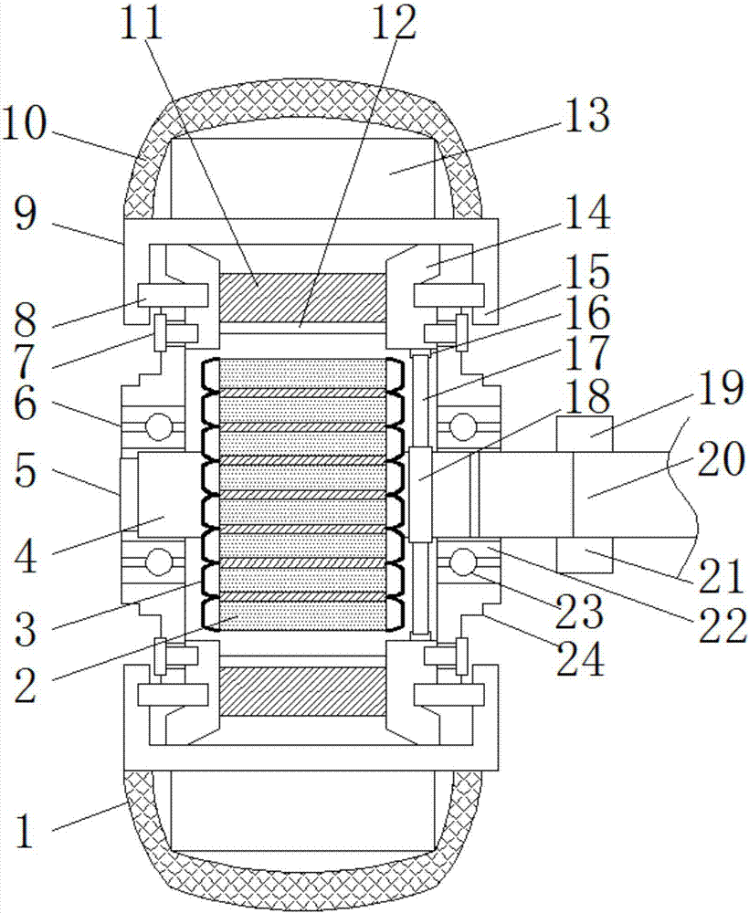
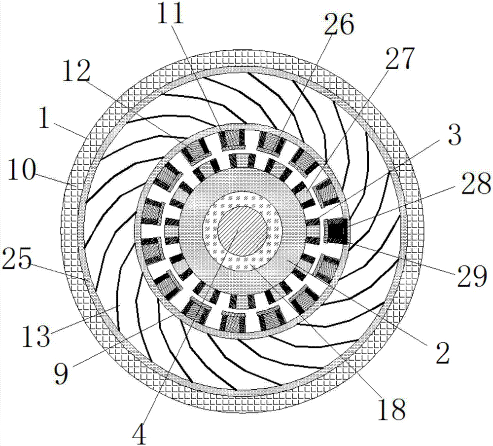
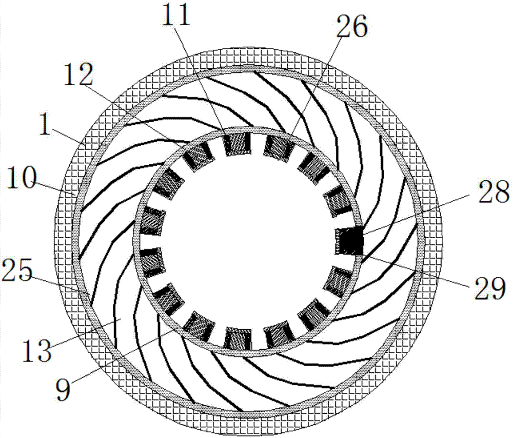
[0025] see Figure 1~5 , in an embodiment of the present invention, a magnetically controlled wheel based on an electromagnetic propulsion system includes a magnetically controlled wheel body 1, a stator core 2, a main shaft 4, a bearing 6, a rotor core 9 and a wear-resistant tire 10, the magnetic The middle part of the control wheel body 1 is equipped with a main shaft 4, the outer end of the main shaft 4 is connected with a shaft cap 5, and the inner end of ...


PUM


Abstract

The invention discloses a magnetic control wheel based on an electromagnetic propulsion system, which comprises a magnetic control wheel body, a stator iron core, a spindle, a bearing piece, a rotor iron core and a wear-resisting tire, wherein the middle part of the magnetic control wheel body is provided with the spindle; the outer end of the spindle is connected with a spindle cap; the inner end of the spindle is welded with a fixing shaft; the stator iron core is welded on the spindle; the outer side surface of the stator iron core is provided with a plurality of protruding claw poles; a stator winding is wound on the claw pole; the stator iron core is sleeved with the rotor iron core; the inner wall of the rotor iron core is provided with a plurality of rotor tooth poles; and an excitation winding is wound on the rotor tooth pole. The assembling is convenient, the shock absorption performance of the magnetic control wheel body is improved, the movement of the magnetic control wheel body is realized, the consumed energy is provided through conversion by electric energy, the speed of the existing vehicle is improved, the bearing piece increases rotation stability of the rotor iron core, a plurality of tire surface inner supporting pieces, a magnetic insulation ring and the wear-resisting tire, the magnetic control wheel body can be driven to rotate reversely conveniently, and steering of the magnetic control wheel body is realized.

Description

technical field [0001] The invention relates to the technical field of vehicles, in particular to a magnetic control wheel based on an electromagnetic propulsion system. Background technique [0002] Existing vehicle devices are provided with wheels. The wheel in the existing structure is usually composed of a wheel shaft, a wheel hub, a rim, and a tire. The outer circumference of the wheel hub usually uses a rubber tire and keeps it inflated by means of inflation. Once the inflation is insufficient or deflated, the wheel will not be able to drive. When driving on the road surface, the potholes will cause the vehicle to bump, and the cushioning performance of the wheels themselves is extremely poor, so an additional shock absorption system is required. Existing wheels, especially in automotive applications, are usually driven by the vehicle's drive system to drive the wheel shaft to rotate, and the wheel is driven to rotate to realize the driving of the vehicle, and gasolin...

Claims


Application Information

Patent Timeline
Patent Type & Authority Applications(China)
IPC IPC(8): H02K7/14H02K1/14H02K1/24H02K1/30H02K3/20H02K7/08H02K13/02H02K13/00B60K7/00
CPCB60K7/0007B60K2007/0092H02K1/145H02K1/243H02K1/30H02K3/20H02K7/086H02K7/14H02K13/00H02K13/02B60K2007/0038H02K13/003H02K19/10H02K5/24H02K7/006H02K7/088H02K23/24
Inventor 张功庆其他发明人请求不公开姓名
Owner XUZHOU XUANKE AGRI MASCH CO LTD
Why Eureka
Try Eureka