
Cone yarn automatic conveying mechanism

An automatic conveying and bobbin technology, which is applied in the field of textile processing, can solve problems such as enlarged structural size, difficult synchronous rotation, and yarn tearing, and achieves the effects of compact structure, stable chain transmission, and high stability

Inactive Publication Date: 2017-11-21
嘉兴正联纺织股份有限公司
View PDF11 Cites 3 Cited by
  • Summary
  • Abstract
  • Description
  • Claims
  • Application Information

AI Technical Summary

Problems solved by technology

[0003] In textile processing, the pay-off roller and take-up roller in our common textile equipment are generally driven by different driving devices, so it is difficult to ensure that the two can rotate synchronously. If there is a speed difference between the two during operation , the spinning thread will be subjected to a momentary pulling force, which will easily cause the thread to be torn off. At the same time, the existing tensioning device generally only has a tensioning wheel to compress the spinning thread. Relatively large, resulting in larger overall structure size

Method used


Image

  • Cone yarn automatic conveying mechanism
  • Cone yarn automatic conveying mechanism

Examples


Embodiment Construction

[0017] The following will clearly and completely describe the technical solutions in the embodiments of the present invention with reference to the accompanying drawings in the embodiments of the present invention. Obviously, the described embodiments are only some, not all, embodiments of the present invention.

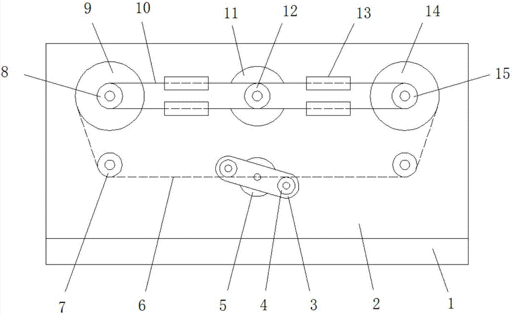
[0018] refer to Figure 1-2 , an automatic bobbin conveying mechanism, comprising a base plate 1, a fixed plate 2 is installed on the top of the base plate 1, and a first rotating shaft, a second rotating shaft, a third rotating shaft, a guide 13, and a first motor are installed on the side of the fixing plate 2 11 and the second motor 5, a pay-off roller 9 and a second driven sprocket 8 are installed on the second rotating shaft, a take-up roller 14 and a first driven sprocket 15 are installed on the first rotating shaft, the first motor Drive sprocket 12 is installed on the output shaft of 11, is connected with chain 10 between drive sprocket 12, the first driven s...


PUM


Abstract

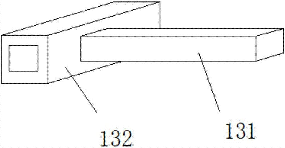
The invention discloses a cone yarn automatic conveying mechanism. The cone yarn automatic conveying mechanism comprises a bottom plate. A fixing plate is mounted at the top of the bottom plate. A first rotary shaft, a second rotary shaft, two third rotary shafts, four guiders, a first motor and a second motor are mounted on the side edge of the fixing plate. A pay-off roller and a second driven chain wheel are mounted on the second rotary shaft. A take-up roller and a first driven chain wheel are mounted on the first rotary shaft. A driving chain wheel is mounted on an output shaft of the first motor. A chain is connected among the driving chain wheel, the first driven chain wheel and the second driven chain wheel. Each guider comprises a fixing rod and a guide sleeve; one end of each fixing rod is mounted on the fixing plate; each guide sleeve is mounted at the other end of the corresponding fixing rod; and the chain is connected with the guide sleeves in a sleeving mode. Guiding wheels are mounted on the third rotary shafts. The spinning efficiency is improved, the structure is quite compact, transmission is stable, and the system operation stability is quite high.

Description

technical field [0001] The invention relates to the technical field of textile processing, in particular to an automatic bobbin conveying mechanism. Background technique [0002] The original meaning of textile is taken from the general term of spinning and weaving, but with the continuous development and improvement of the textile knowledge system and subject system, especially after the emergence of non-woven textile materials and three-dimensional composite weaving technologies, the current textile is not only a traditional Hand spinning and weaving also include garment, industrial and decorative textiles produced by non-woven technology, modern three-dimensional weaving technology, and modern electrostatic nano-netting technology. Therefore, modern textile refers to a multi-scale structure processing technology of fibers or fiber aggregates. [0003] In textile processing, the pay-off roller and take-up roller in our common textile equipment are generally driven by diff...

Claims


Application Information

Patent Timeline
Patent Type & Authority Applications(China)
IPC IPC(8): B65H57/14B65H54/74B65H59/10B65H49/18
CPCB65H57/14B65H49/18B65H54/74B65H59/10B65H2701/31
Inventor 陆雪青
Owner 嘉兴正联纺织股份有限公司
Learn More