
a pot structure

A pot body and pot spout technology, applied in the field of pot body structure, can solve the problems of high tension of the metal shell, insufficient strength of the double-layer electric kettle shell and easy deformation, affecting the user experience, etc., and achieve the effect of easily covering the opening by the handle

Active Publication Date: 2020-10-02
JOYOUNG CO LTD
View PDF6 Cites 0 Cited by
  • Summary
  • Abstract
  • Description
  • Claims
  • Application Information

AI Technical Summary

Problems solved by technology

Taking an electric kettle as an example, the body temperature of a single-layer electric kettle is relatively high, and the user is easily burnt by touching the shell, and the heat preservation and heating efficiency is not high; the double-layer electric kettle includes an inner tank and an outer shell, and There is an opening, the assembly method is to pull the opening of the shell, then put the shell directly outside the inner tank, and then cover the opening with the handle and clamp the outer shell to connect with the inner tank, but before the handle is installed, the outer shell cannot be used due to its own tension. In the closed state, the assembly of the handle is inconvenient, which affects the production efficiency of the electric kettle
[0003] The double-layer electric kettle also has the problem that the shell strength is not enough and easy to deform, which affects the aesthetics of the electric kettle body
Especially when the shell is a metal shell, the tension of the metal shell at the opening is greater, and it is more difficult to install the handle, and if there is no support to support the body of the pot, the shell is vulnerable to external force impact during the user's use or transportation. Concave, affecting the aesthetics of the pot body
On the other hand, due to the low plasticity of metal, if the thickness of the metal shell is increased to increase the strength of the metal shell, the cost of the electric kettle will increase, and the electric kettle will become heavier, which will affect the user experience

Method used


Image

  • a pot structure
  • a pot structure
  • a pot structure

Examples


Embodiment 1

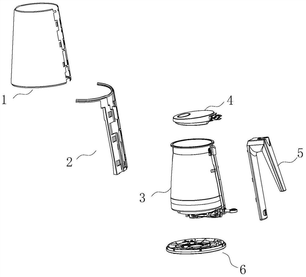
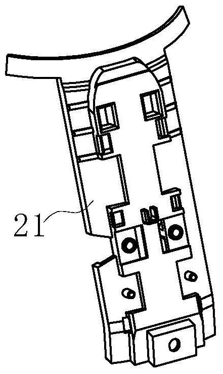
[0046] Such as Figure 1-Figure 2 As shown, a pot body structure, the pot body includes an inner tank 3, a metal shell 1, a handle 5, an opening is provided on one side of the metal shell 1, and the metal shell 1 is sleeved outside the inner tank 3 , the kettle body also includes a plastic bracket 2 arranged between the metal shell 1 and the inner tank 3, the plastic bracket 2 is used to support the metal shell 1, and the plastic bracket 2 includes a first bracket 21. The first bracket 21 is arranged at the opening and axially arranged along the outer wall of the inner container 3, and the handle 5 covers the opening. It should be noted that the first bracket 21 is axially arranged along the outer wall of the inner container 3 (the height direction of the inner container 3 is taken as the axial schematic illustration) should be understood in a broad sense, for example, including that the first bracket 21 is parallel to the axial direction, and at the same time It may also inc...

Embodiment 2

[0064] When there is a large gap between the metal shell 1 and the inner tank 3, if there is no supporting member to support the pot body during the user's use or transportation, the metal shell 1 is easily impacted by external force and causes indentation, which affects the appearance of the pot body sex.

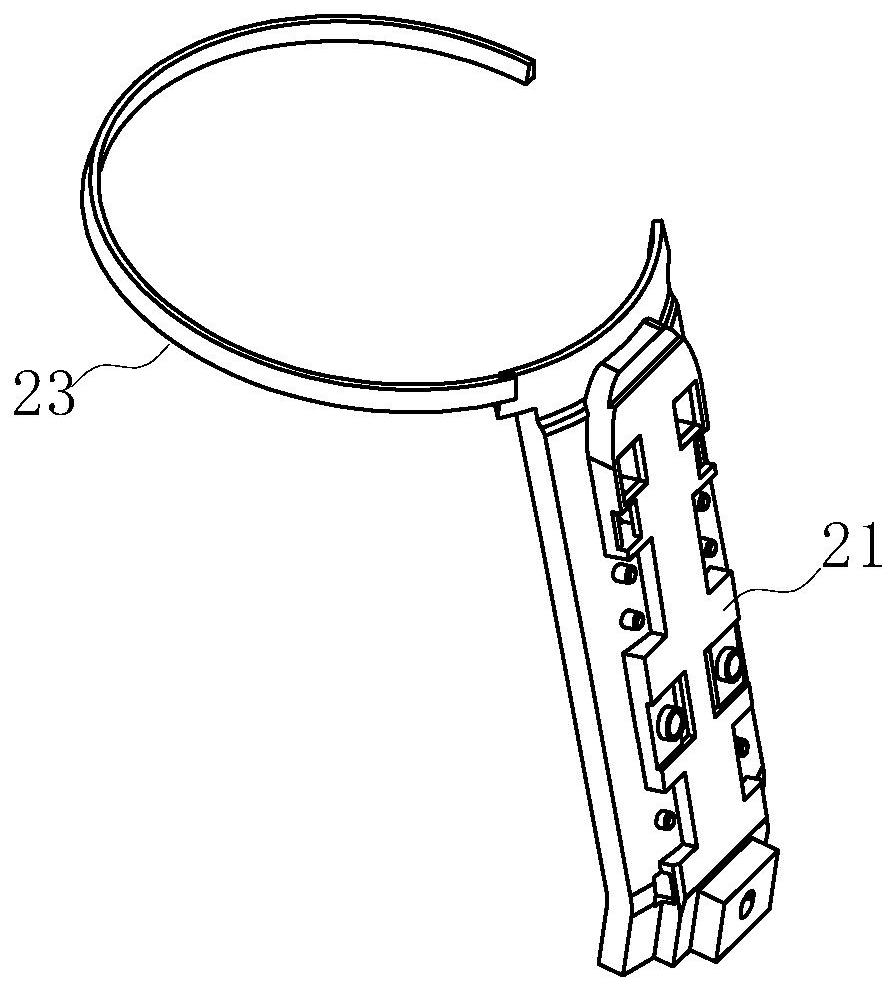
[0065] Based on the structure of embodiment 1, such as Figure 3-4 As shown, further, the plastic bracket 2 also includes a second bracket, which is a first extension bracket connected to one side of the first bracket 21 and extending circumferentially along the outer wall of the inner container 3 twenty three. It should be explained that the "circumferential direction" in "the second bracket is the first extension bracket 23 connected to the side of the first bracket 21 and extending along the outer wall of the inner container 3" (to surround the inner container 3 axis direction is a schematic illustration of the circumferential direction) should be understood in a broa...

Embodiment 3

[0080] Based on the structure described in embodiment 1 or 2, such as Figure 5 As shown further, when the size of the above-mentioned metal casing 1 is inconsistent up and down, the overall strength of the metal casing 1 is inconsistent, especially when the above-mentioned second installation port is large, the strength of the lower part of the metal casing 1 is weak, easy to deform, and cannot maintain its round shape. shape, in addition to increasing the ring bracket 24 described in embodiment 2 to strengthen the strength of the lower part of the metal shell 1, the base 6 can also be used to strengthen the strength. The base 6 can be shaped like a bowl, and its height is preferably 30 mm to 40 mm, so as to increase the overall rigidity of the base 6 , that is, the base 6 itself has enough rigidity to support the metal shell 1 .

[0081] Further, the above-mentioned bowl-shaped base 6 is provided with reinforcements, and a plurality of reinforcements are arranged at interval...


PUM


Abstract

The invention relates to household appliances, in particular to a kettle body structure. A kettle body comprises a liner, a shell, a handle and a base. An opening is formed in one side of the shell. The liner is sleeved with the shell. The shell is a metal shell. The kettle body further comprises a plastic support arranged between the metal shell and the liner. The plastic support is used for supporting the metal shell and comprises a first support. The first support is axially arranged at the opening along the outer wall of the liner. The handle covers the opening. The kettle body structure is low in cost and convenient to assemble and is more conveniently and more safely used.

Description

technical field [0001] The invention relates to a household appliance, in particular to a kettle body structure. Background technique [0002] At present, there are more and more double-layer kettle body structures on the market, especially widely used in liquid heaters such as electric kettles and soybean milk machines. Taking an electric kettle as an example, the body temperature of a single-layer electric kettle is relatively high, and the user is easily burnt by touching the shell, and the heat preservation and heating efficiency is not high; the double-layer electric kettle includes an inner tank and an outer shell, and There is an opening, the assembly method is to pull the opening of the shell, then put the shell directly outside the inner tank, and then cover the opening with the handle and clamp the outer shell to connect with the inner tank, but before the handle is installed, the outer shell cannot be used due to its own tension. Being in a closed state causes in...

Claims


Application Information

Patent Timeline
Patent Type & Authority Patents(China)
IPC IPC(8): A47J27/21A47J31/44A47J31/54
CPCA47J27/21166A47J31/4403A47J31/54
Inventor 朱泽春张乐杨夫健李军
Owner JOYOUNG CO LTD
Learn More