Metasurface terahertz dynamic reflective polarization modulator

A polar modulator and terahertz technology, applied in the direction of waveguide devices, electrical components, circuits, etc., can solve the problems of limited application range, conversion efficiency needs to be further improved, conversion efficiency and frequency tuning range need to be improved, and achieve The effect of multiple working frequency points

Inactive Publication Date: 2017-11-17
UNIV OF ELECTRONICS SCI & TECH OF CHINA
View PDF1 Cites 25 Cited by
  • Summary
  • Abstract
  • Description
  • Claims
  • Application Information

AI Technical Summary

Problems solved by technology

[0003] In 2015, TLv et al proposed a new type of thermal switch to control THz wave propagation based on phase change (TTLv, LiZ, Sun B, etal.Chiral metamaterial with VO 2 inclusions for thermally manipulating cross-polarization[J].Applied Optics&Photonics China,2015,9673) created an ultra-thin metamaterial consisting of an array of 90° twisted E-type resonators doped with vanadium dioxide to achieve thermally controlled cross-polarization Polarization conversion, but this structure only realizes the modulation of the amplitude of the cross-polarized transmission coefficient, which also limits the scope of use of the structure, and the conversion efficiency needs to be further improved
In 2016, D.C.Wang et al embedded VO in the metasurface SRR structure 2 Materials (D.C.Wang, L.C.Zhang, Y.D.Gong, L.K.Jian, T.Venkatesan, C.W.Qiu, M.H.Hong, Multiband SwitchableTerahertz Quarter-Wave Plates via Phase-ChangeMetasurfaces, IEEE PhotonicsJournal, 8(1):5500308, 2016.) realized Dynamic adjustment of linear polarization to circular polarization conversion in terahertz multi-band, but its conversion efficiency and frequency tuning range need to be improved

Method used


Image

  • Metasurface terahertz dynamic reflective polarization modulator
  • Metasurface terahertz dynamic reflective polarization modulator
  • Metasurface terahertz dynamic reflective polarization modulator

Examples


Embodiment

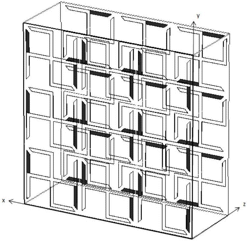
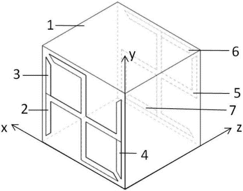
[0048] A dynamically tunable terahertz reflective polarization converter based on metasurfaces, such as figure 1 and figure 2 As shown, the metal chiral structure including the substrate dielectric substrate and the metal chiral structure periodically arranged on the surface of the substrate dielectric substrate; the chiral metasurface structure includes a dielectric material layer and two layers of metal chiral structure surface layers; the two layers The metal chiral structure surface layer is located on both sides of the dielectric material layer. Each metal chiral structure surface layer is composed of resonant units arranged in a periodic square. The resonant unit arrangement structure of the two metal chiral structure surface layers is the same, and the shape structure mutual conjugate structure;

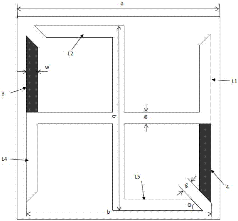
[0049] see image 3 , the polarization structure unit of the metasurface terahertz dynamic reflective polarization modulator includes a substrate dielectric substrate, a fr...


PUM


Abstract

The invention discloses a metasurface terahertz dynamic reflective polarization modulator and relates to the technical field of electromagnetic wave full-vector transmission control devices. The metasurface terahertz dynamic reflective polarization modulator comprises a polarization structure unit. The polarization structure unit comprises a substrate dielectric substrate, a front resonant structure arranged on the front side of the substrate dielectric substrate, and a back resonant structure on the back side of the substrate dielectric substrate, wherein the front resonant structure and the back resonant structure have the same structure and are 90-dgree conjugate. The front resonant structure includes the following sides: a first metal side disposed at the right of a first quadrant, a second metal side disposed at the top of a second quadrant, a first metal oxide side disposed at the left of the second quadrant, a fourth metal side disposed at the left of a third quadrant, a fifth metal side disposed at the bottom of a fourth quadrant, and a second metal oxide side disposed at the right of the fourth quadrant, wherein the projections of the above sides on the substrate dielectric substrate are right-angled trapezoids, the waists of the right-angled trapezoids all point to a center of symmetry area and each right-angled trapezoid has a right-angled edge parallel to the x-axis. The metasurface terahertz dynamic reflective polarization modulator realizes electromagnetic wave polarization control on a ultra-thin scale.

Description

technical field [0001] The invention belongs to the technical field of electromagnetic wave full-vector transmission control devices, in particular to a dynamically adjustable terahertz reflective polarization converter based on a metasurface. Background technique [0002] Terahertz (THz) technology has developed rapidly in the fields of security detection, wireless communication, non-destructive testing, and imaging. High-performance terahertz polarization control devices are the core devices of terahertz communication, imaging and detection systems, and have important application value in high-tech fields such as communication, navigation, radar, and guidance. Polarization control devices made of traditional electromagnetic materials are mainly based on traditional optical theories such as the Faraday effect and birefringence principles, which require a long propagation distance, an external magnetic field, and a complex structure to produce phase delay or polarization rot...

Claims


Application Information

Patent Timeline
Patent Type & Authority Applications(China)
IPC IPC(8): H01P1/165H01P1/17
CPCH01P1/165H01P1/17
Inventor 兰峰武晓芳杨梓强史宗君
Owner UNIV OF ELECTRONICS SCI & TECH OF CHINA
Why Eureka
Try Eureka