Eureka AIR delivers breakthrough ideas for toughest innovation challenges, trusted by R&D personnel around the world.

Automatic loading device for high current component testing

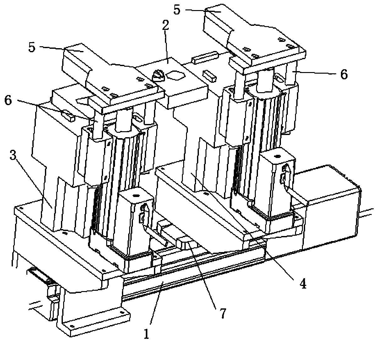
An automatic loading, high current technology, applied in the direction of measuring device, measuring device casing, electrical measuring instrument parts, etc., can solve the problems of damage to the appearance of the shunt, high labor intensity, low efficiency, etc., to reduce the occurrence of work-related injuries. The effect of reducing labor intensity and improving production efficiency

Active Publication Date: 2020-08-14
ELECTRIC POWER RESEARCH INSTITUTE OF STATE GRID SHANDONG ELECTRIC POWER COMPANY +2
View PDF14 Cites 0 Cited by
  • Summary
  • Abstract
  • Description
  • Claims
  • Application Information

AI Technical Summary

Problems solved by technology

[0003] The current problems in the above structural design are: first, manual clamping, first of all manually adjust the position of the diverter support platform to ensure that the position of the diverter positioning hole is consistent with the bolt hole position of the support platform, the action is cumbersome and inefficient; the second is wrench tightening Bolts, make the bolts press the shunt tightly to ensure that the shunt and the wiring lug are tightly fitted. In order to pass through the large current, generally the shunt will be slightly deformed when it is pressed strongly, and the shunt will generally be damaged when it is tightened strongly. The appearance of the surface; the third is to tighten the wrench, labor-intensive

Method used


Image

  • Automatic loading device for high current component testing
  • Automatic loading device for high current component testing
  • Automatic loading device for high current component testing

Examples


Embodiment Construction

[0029] It should be pointed out that the following detailed description is exemplary and intended to provide further explanation to the present application. Unless defined otherwise, all technical and scientific terms used herein have the same meaning as commonly understood by one of ordinary skill in the art to which this application belongs.

[0030] It should be noted that the terminology used here is only for describing specific implementations, and is not intended to limit the exemplary implementations according to the present application. As used herein, unless the context clearly dictates otherwise, the singular is intended to include the plural, and it should also be understood that when the terms "comprising" and / or "comprising" are used in this specification, they mean There are features, steps, operations, means, components and / or combinations thereof.

[0031] The present invention will be further described below in conjunction with accompanying drawing and embodi...


PUM


Abstract

The invention relates to an automatic loading device for heavy current element tests. The device comprises an electric sliding table used for disposing a fixed supporting device and a moveable supporting device of a tested workpiece, and two compaction devices used for compacting the tested workpiece, wherein the tested workpiece is arranged at a top end of the fixed supporting device and the moveable supporting device, the fixed supporting device is fixed on the electric sliding table, the moveable supporting device is arranged on the electric sliding table and can move on the electric sliding table relative to the fixed supporting device so as to dispose tested workpieces in different sizes, and the two compaction devices are respectively arranged on the fixed supporting device and the moveable supporting device and are used for compacting the tested workpiece from the upper portion. The loading device is advantaged in that automatic adjustment can be carried out according to the sizes of the workpieces, and damage to the tested workpieces can be reduced.

Description

technical field [0001] The invention belongs to the field of electric energy testing, and in particular relates to an automatic loading device for testing large current components. Background technique [0002] At present, in the electric energy test experiment, taking the shunt as an example, there are many kinds of shunts for domestic DC electric energy verification, such as figure 1 As shown, the specifications and sizes are different. At present, the method used in domestic shunt verification is manual wrench tightening, and the bolts are strongly pressed, such as figure 2 As shown, ensure that the shunt is in full contact with the wiring lug, so that it can safely pass a large current and ensure that the contact part does not heat up. [0003] The current problems in the above structural design are: first, manual clamping, first of all manually adjust the position of the diverter support platform to ensure that the position of the diverter positioning hole is consist...

Claims


Application Information

Patent Timeline
Patent Type & Authority Patents(China)
IPC IPC(8): G01R1/04
CPCG01R1/04G01R1/0408
Inventor 张红范巧成周新华王莉邱全锋林昱马俊孙宁赫姜荣华单红红
Owner ELECTRIC POWER RESEARCH INSTITUTE OF STATE GRID SHANDONG ELECTRIC POWER COMPANY
Why Eureka
Eureka Blog
Learn More