Low-power centrifugal pump directly driven by permanent-magnet synchronous motor

A permanent magnet synchronous motor technology, applied to synchronous motors with stationary armatures and rotating magnets, drive pumps, AC motor control, etc., can solve problems such as complex detection circuits and programs

Active Publication Date: 2017-11-17
HANYU GRP CO LTD
View PDF5 Cites 2 Cited by
  • Summary
  • Abstract
  • Description
  • Claims
  • Application Information

AI Technical Summary

Problems solved by technology

The first step of this control is pre-positioning—determine the position of the magnetic poles of the permanent magnet rotor relative to the magnetic poles of the stator, and then apply a

Method used


Image

  • Low-power centrifugal pump directly driven by permanent-magnet synchronous motor
  • Low-power centrifugal pump directly driven by permanent-magnet synchronous motor
  • Low-power centrifugal pump directly driven by permanent-magnet synchronous motor

Examples


Embodiment Construction

[0043] The centrifugal pump according to the first embodiment of the present invention is improved on the basis of the embodiment described in the published specification of the applicant's previous application CN201510650496.1.

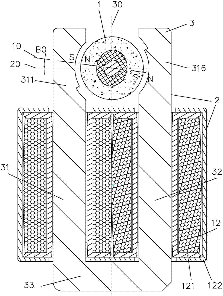
[0044] The basic mechanical structure of the centrifugal pump according to the first embodiment of the present invention is as follows: Figure 7 As shown, it inherits from CN201510650496.1 published manual figure 1 The structure shown includes:

[0045] ——U-shaped iron core single-phase permanent magnet synchronous motor ( figure 1 The laminated core 3 and winding 12 of the motor stator and the cross section of the permanent magnet rotor 1) and the centrifugal impeller 105 whose rotating shaft is coaxially coupled via a starting mechanism are shown. The centrifugal impeller 105 has 4 blades; according to the water pressure requirements, the number of blades can also be 3, 5 or 6, but preferably no more than 8 blades, and if an odd number of blades...


PUM

PropertyMeasurementUnit
Diameteraaaaaaaaaa

Abstract

A low-power centrifugal pump directly driven by a permanent-magnet synchronous motor comprises a centrifugal impeller and the motor, wherein the centrifugal impeller rotates in a fixed direction; the motor drives the impeller coaxially, a stator winding of the motor is connected with an alternating-current power supply in a specified winding direction, a rotor is a permanent-magnet rotor, and the number of poles of the rotor is the same as that of a stator; and in the free state, the axes of all the poles of the rotor deflect by certain acute angles in a preset deflection direction with the axis of the pole closest to the stator as the reference. The alternating-current power supply supplies power to the stator winding through a switch controlled by a control circuit. The number of the poles of the stator is two, and the diameter of the impeller is not larger than 70 mm; or the number of the poles of the stator is four, and the diameter of the impeller is not larger than 100 mm. A program set in the control circuit comprises the step that the switch is driven according to a detected signal to control the alternating-current power supply to supply power to the stator winding. Before the centrifugal pump starts, one pole surface of a stator core has the magnetism with the specified polarity. Through the design, the process of pre-positioning detection when a centrifugal pump starts in the prior art is omitted, the performance is improved, and the cost is reduced.

Description

technical field [0001] The invention relates to a low-power centrifugal pump directly driven by a permanent magnet synchronous motor, in particular to the coordination of its mechanical structure, electromagnetic structure and control method; the IPC classification belongs to F04D25 / 06. Background technique [0002] In view of the fact that the centrifugal pump is driven by an asynchronous motor and the efficiency is low, the low-power centrifugal pump proposed by the applicant's previous application CN201510650496.1 is directly driven by a permanent magnet synchronous motor, which is energy-saving and small in size, and is in a predetermined rotation direction. It has better starting and running performance, and does not need to provide a separate rotor position detection element. However, in order for the centrifugal pump to start running in the predetermined direction, it is necessary to control its energization. The first step of the control is pre-positioning—determini...

Claims


Application Information

Patent Timeline
IPC IPC(8): F04D13/06F04D29/22F04D15/00F04D9/00H02K21/14H02K1/14H02P25/022
CPCF04D9/004F04D13/06F04D15/00F04D29/22H02K1/14H02K21/14H02K2201/03H02K2213/03H02P25/024
Inventor 叶露微
Owner HANYU GRP CO LTD
Why Eureka
Try Eureka