Annular blowout preventer

A technology of annular blowout preventer and annular protrusion, which is applied in the direction of wellbore/well components, earthwork drilling and production, sealing/isolation, etc., can solve problems such as prolonging the time of minor repair operations, destroying reservoirs, killing wells, etc., and achieves Shorten the lifting time of tubing, protect the reservoir, and shorten the time

Pending Publication Date: 2017-11-17
CHINA UNITED COALBED METHANE +1
View PDF17 Cites 8 Cited by
  • Summary
  • Abstract
  • Description
  • Claims
  • Application Information

AI Technical Summary

Problems solved by technology

[0004] In the prior art, the annular blowout preventer adopts a hydraulic annular blowout preventer. When the oil pipe is lifted in a minor repair operation, the diameter of the oil pipe coupling used to connect the adjacent oil pipes is relatively large, and the hydraulic annular preventer cannot pass through directly. When the oil pipe collar When passing through the hydraulic annulus BOP, the hydraulic annulus BOP used for the passage of the oil pipe coupling needs to be closed to allow the passage of the oil pipe coupling, while other hydraulic annulus BOPs that cooperate with the oil pipe need to be opened In order to ensure the sealing of the annular space between the oil pipe and the casing, through the above-mentioned method of using multiple hydraulic annular BOPs to open and close alternately to realize the passage of the oil pipe coupling, it is necessary to wait for the opening and closing of the hydraulic annulus BOPs, resulting in It takes a long time for the tubing to be lifted up for minor repair operations, which prolongs the time of minor repair operations and reduces the efficiency of minor repair operations. At the same time, due to the water production characteristics of coalbed methane reservoirs, too long workover time will also cause actual well killing and damage. Reservoir in snubbing operations

Method used


Image

  • Annular blowout preventer

Examples


Embodiment Construction

[0036] The invention discloses an annular blowout preventer, which can shorten the time of minor repair operation, improve the efficiency of minor repair operation and protect the reservoir in snubbing operation.

[0037] The following will clearly and completely describe the technical solutions in the embodiments of the present invention with reference to the accompanying drawings in the embodiments of the present invention. Obviously, the described embodiments are only some, not all, embodiments of the present invention. Based on the embodiments of the present invention, all other embodiments obtained by persons of ordinary skill in the art without making creative efforts belong to the protection scope of the present invention.

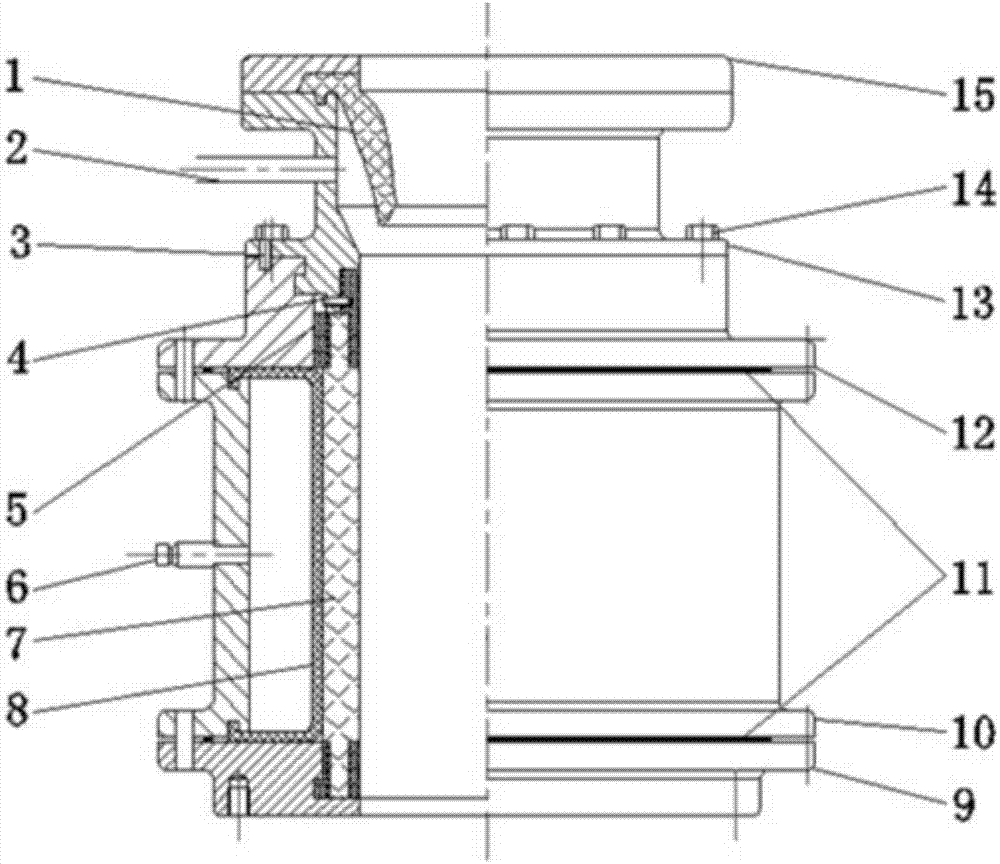
[0038] see figure 1 , figure 1 Schematic diagram of the structure of the annular blowout preventer provided by the embodiment of the present invention.

[0039] The invention discloses an annular blowout preventer, which comprises a first casing 1...


PUM


Abstract

The invention discloses an annular blowout preventer. The annular blowout preventer comprises a first shell body, a gas bag and a gas inflating opening. According to the technical schemes of the annular blowout preventer, gas serves as a power medium to push the gas bag to embrace an oil tube tightly, the gas is inflated between the first shell body and the gas bag through a gas inflating valve, the gas bag is deformed and embraces the oil tube tightly, so that annular sealing between the oil tube and a sleeve tube is achieved; when the oil tube is needed to be lifted upwardly during minor repairing operation, due to the fact that compressibility of the gas is good, the gas bag can be squeezed by an oil tube coupling, the gas located between the gas bag and the first shell body is squeezed and deformed, so that space in the middle of the gas bag allows the oil tube coupling to pass through directly; and compared with the prior art, time for waiting opening and closing of a hydraulic annular blowout preventer is saved, so that oil tube uplifting time in minor repairing operation is shortened, and time of minor repairing operation is reduced accordingly, the efficiency of minor repairing operation is improved, and reservoir in non-well killing operation is protected.

Description

technical field [0001] The invention relates to the technical field of coal bed gas exploitation, in particular to an annular blowout preventer. Background technique [0002] Snubbing operation is an operation method in which professional technicians operate special equipment to trip strings in a pressurized environment. [0003] Snubbing equipment includes workbench, lifting system, slip group and blowout preventer group, where the blowout preventer group includes annular blowout preventer and pressure relief / balance spool. [0004] In the prior art, the annular blowout preventer adopts a hydraulic annular blowout preventer. When the oil pipe is lifted in a minor repair operation, the diameter of the oil pipe coupling used to connect the adjacent oil pipes is relatively large, and the hydraulic annular preventer cannot pass through directly. When the oil pipe collar When passing through the hydraulic annulus BOP, the hydraulic annulus BOP used for the passage of the oil pi...

Claims


Application Information

Patent Timeline
Patent Type & Authority Applications(China)
IPC IPC(8): E21B33/06
CPCE21B33/06
Inventor 吴建光毛正义张健綦耀光郭晖朱洪迎张兵张芬娜孟尚志
Owner CHINA UNITED COALBED METHANE
Why Eureka
Try Eureka