Paper money or bill authenticity identification method
A technology for bills and banknotes, which is applied in the field of banknote or bill identification and detection. It can solve the problems of high system cost, easy falling off of silver plating, inconsistent imaging, etc., and achieve clear front images, increase color effects, and enhance front light intensity. Effect
- Summary
- Abstract
- Description
- Claims
- Application Information
AI Technical Summary
Problems solved by technology
Method used
Image
Examples
Embodiment 1
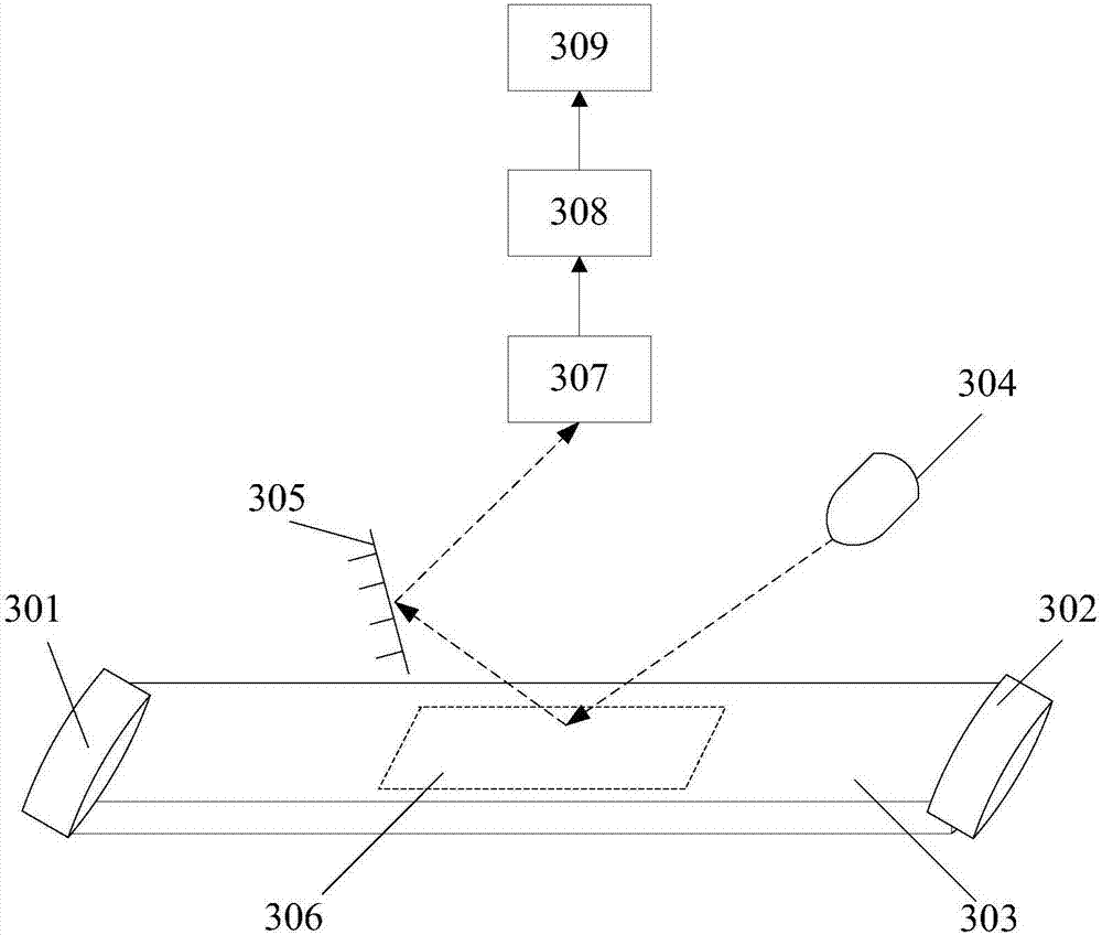
[0034] The embodiment of the present invention provides a counterfeit device for banknotes or bills, such as image 3 shown, including:
[0035] Cash outlet 301;
[0036] Money inlet 302;
[0037] A banknote feeding channel 303 located between the banknote outlet 301 and the banknote inlet 302;
[0038] An incident light source 304 and a total reflection prism 305 arranged on both sides of the note feeding channel 303;
[0039] A photoelectric receiver 307 arranged directly above the area to be detected 306 in the banknote delivery channel 303;
[0040] A photoelectric signal amplifying circuit 308 connected to the photoelectric receiver 307;
[0041] A signal comparison circuit 309 connected to the photoelectric signal amplification circuit 308 .
[0042] Wherein, the incident light source 304 is located obliquely above the area to be detected 306 in the banknote feeding channel 303, and irradiates the area to be detected 306 at a preset oblique angle; between the refle...
Embodiment 2
[0054] Such as Figure 4 Shown, this embodiment also includes with respect to embodiment one:
[0055] A beam splitter 410 is further arranged between the photoelectric receiver 407 and the region 406 to be detected, and the beam splitter 410 performs semi-transparent and semi-reflective light emitted by the incident light source 404 .
[0056] Wherein, the beam splitter plate 410 and the plane of the region to be detected 406 are arranged to form a preset angle.
[0057] Preferably, the beam splitter 410 should be located directly below the photoelectric receiver 407, at the same height as the incident light source 404, and the end of the beam splitter 410 close to the incident light source 404 is higher than the reference plane at an angle of 45 degrees, the beam splitter The plate 410 semi-transparently reflects the light emitted by the incident light source 404; the photoelectric receiver 407 can collect images through the beam splitter plate 410; after the light beam emi...
Embodiment 3
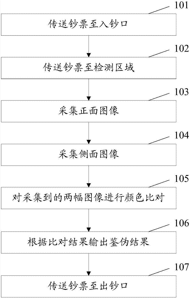
[0060] Figure 5 It shows the process of authenticating banknotes or bills to be detected by using the authenticating device of the present invention.
[0061] The system starts, receives banknotes from the banknote inlet, and transmits them to the preset position (area to be detected) through the banknote feeding channel, and collects images of the banknotes that arrive at this area, and the collected images include the reflected light imaging of the light source in the area to be detected , and the reflected light of the light source in the area to be detected is then reflected by the total reflection prism to form an image. After that, extract the color-changing anti-counterfeiting features of banknotes in the image, remove the background color, and determine the color values of the two color-changing anti-counterfeiting features of a frame of image, by comparing the difference between the front feature color value, the side feature color value and the front side feature ...
PUM
 Abstract
Description
Claims
Application Information
 - Generate Ideas
- Intellectual Property
- Life Sciences
- Materials
- Tech Scout
- Unparalleled Data Quality
- Higher Quality Content
- 60% Fewer Hallucinations
Browse by: Latest US Patents, China's latest patents, Technical Efficacy Thesaurus, Application Domain, Technology Topic, Popular Technical Reports.
© 2025 PatSnap. All rights reserved.Legal|Privacy policy|Modern Slavery Act Transparency Statement|Sitemap|About US| Contact US: help@patsnap.com


