A kind of automatic reset device of sewing machine bottom thread detection sensor and sewing machine
A detection sensor, automatic reset technology, applied in the direction of bobbin winding, sewing equipment, sewing machine components, etc. in sewing machines, can solve the problems of sensor signal reception deviation, easy to touch the sensor, affecting detection accuracy, etc., to ensure accuracy. , the effect of reducing labor intensity and improving accuracy
- Summary
- Abstract
- Description
- Claims
- Application Information
AI Technical Summary
Problems solved by technology
Method used
Image
Examples
Embodiment 1
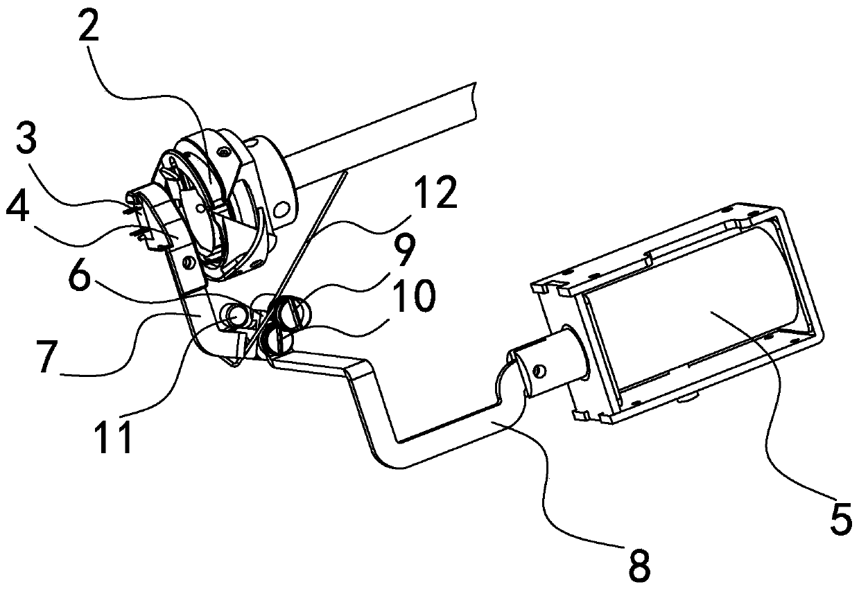
[0035] Such as figure 1 , 2 As shown in and 3, the sewing machine includes a bottom plate 1 and a rotary hook 2, the rotary hook 2 includes a bobbin case and a bobbin, and there is a gap on the bobbin case. The sensor 3 and the reset mechanism on 4, the reset mechanism can put the sensor 3 in the detection state or the shuttle change state. The detection state is that the sensor 3 is close to and facing the notch of the bobbin case to detect the bobbin thread margin on the bobbin. The state of changing the hook is that the sensor 3 and the sensor holder 4 are away from the rotary hook 2 for a period of time so as to reserve a large space for changing the hook.
[0036] Reset mechanism comprises reset transmission structure, controller and the electromagnet that is connected with controller, and the electromagnet of present embodiment is push-pull type electromagnet-5, and the controller of present embodiment is the electric control box of sewing machine, certainly its control...
Embodiment 2
[0040] Such as Figure 4 and 5 As shown, the difference between the structure of this embodiment and the first embodiment is that the reset transmission structure includes a rotating bracket 15, an eccentric wheel 16, a reset torsion spring 18 and a pull wire 14, and the rotating bracket 15 is fixedly installed on the bottom plate 1 and its The rotating shaft 17 that can rotate relative to the rotating bracket 15 is installed on the top, the sensor holder 4 is fixedly sleeved and connected with the rotating shaft 17, and the eccentric wheel 16 is fixedly installed on one end of the rotating shaft 17 (its eccentric wheel 16 and the rotating shaft 17 can also be One-piece structure), the electromagnet is a push-pull electromagnet 13, and the two ends of the backguy 14 are fixedly connected with the push-pull electromagnet 13 and the eccentric wheel 16 respectively through the stay wire connecting plate, and one end of the reset torsion spring 18 is connected to the rotating brac...
Embodiment 3
[0044] Such as Figure 6 and 7 As shown, the structure difference between this embodiment and Embodiment 1 is that the reset transmission structure includes a limit bracket 23 and a reset torsion spring 24, the electromagnet is a rotating electromagnet 22, and one end of the sensor holder 4 is fixedly connected to the rotating electromagnetic On the output shaft of iron 22, the limit bracket 23 is fixedly installed on the base plate 1, and the rotating electromagnet 22 is installed on the limit bracket 23, and the limit bracket 23 has a limit support plate one 231 and a limit support plate two 232, reset One end of the torsion spring three 24 is connected to the sensor holder 4, and the other end is connected to the above-mentioned limit support plate one 231, and the reset torsion spring three 24 has the torsional force that makes the sensor holder 4 close to the rotary hook 2. When the sensor 3 is located In the detection state, the sensor fixing frame 4 just abuts against ...
PUM
 Abstract
Description
Claims
Application Information
 - R&D
- Intellectual Property
- Life Sciences
- Materials
- Tech Scout
- Unparalleled Data Quality
- Higher Quality Content
- 60% Fewer Hallucinations
Browse by: Latest US Patents, China's latest patents, Technical Efficacy Thesaurus, Application Domain, Technology Topic, Popular Technical Reports.
© 2025 PatSnap. All rights reserved.Legal|Privacy policy|Modern Slavery Act Transparency Statement|Sitemap|About US| Contact US: help@patsnap.com


