Compression roller mechanism for aluminum foil laminating machine

A pressure roller mechanism and compound machine technology, which is applied in lamination, lamination devices, layered products, etc., can solve the problems that the winding pressure roller cannot adjust the pressure, the aluminum foil is loose, and the compaction effect is not good.

Inactive Publication Date: 2017-11-14
LIANGXI XUZHONG GENERAL MACHINERY DESIGN STUDIO
View PDF1 Cites 0 Cited by
  • Summary
  • Abstract
  • Description
  • Claims
  • Application Information

AI Technical Summary

Problems solved by technology

China patent authorization announcement number: CN 202271631 U, authorization announcement date: 2012.06.13, discloses "winding and pressing roller mechanism of aluminum foil compound machine", which only relies on the self-gravity of the winding and pressing roller located above the winding roller on the aluminum foil For compaction, the aluminum foil will loosen when it is rotated to the bottom, and the pressure of the winding roller cannot be adjusted, so the compaction effect is not good

Method used


Image

  • Compression roller mechanism for aluminum foil laminating machine
  • Compression roller mechanism for aluminum foil laminating machine

Examples


Embodiment Construction

[0015] The following will clearly and completely describe the technical solutions in the embodiments of the present invention with reference to the accompanying drawings in the embodiments of the present invention. Obviously, the described embodiments are only some, not all, embodiments of the present invention.

[0016] Examples of the described embodiments are shown in the drawings, wherein like or similar reference numerals designate like or similar elements or elements having the same or similar functions throughout. The embodiments described below by referring to the figures are exemplary and are intended to explain the present invention and should not be construed as limiting the present invention.

[0017] In describing the present invention, it should be understood that the terms "center", "longitudinal", "transverse", "length", "width", "thickness", "upper", "lower", "front", " Back", "Left", "Right", "Vertical", "Horizontal", "Top", "Bottom", "Inner", "Outer", "Clock...


PUM


Abstract

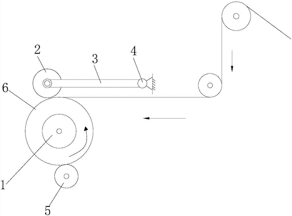
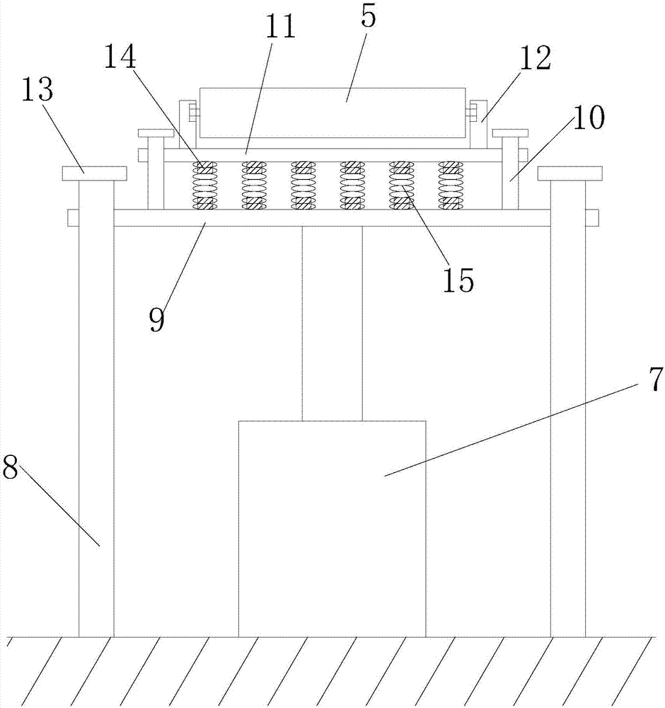
The invention discloses a pressing roller mechanism of an aluminum foil compounding machine, comprising a horizontally positioned and rotatable take-up roller, and further comprising: an upper pressing roller, a lower pressing roller, a lifting mechanism, a guide rod A, a support plate A, a guide rod B. Supporting plate B, bracket and spring, the upper end of the take-up roller is provided with an upper pressure roller in parallel, the upper pressure roller is fixed on the frame through a connecting mechanism, and the lower end of the take-up roller is arranged in parallel with a lower A lifting mechanism is installed below the winding roller, guide rods A are provided on both sides of the lifting mechanism, and through holes A are provided at both ends of the supporting plate A, and the supporting plate A is Both ends are slidably connected to the corresponding guide rod A through the through hole A, the output end of the lifting mechanism is fixedly connected to the bottom of the support plate A, and both ends of the support plate A are fixedly connected to the guide rod B, and the support plate Both ends of B are provided with through holes B. The invention compacts the aluminum foil from the upper and lower directions, which greatly improves the product quality.

Description

technical field [0001] The invention relates to the technical field of metal thin film composite machinery, in particular to a pressure roller mechanism of an aluminum foil composite machine. Background technique [0002] The aluminum foil compounding machine is a special equipment for bonding and compounding aluminum foil and other material films (such as PET film, copper foil, etc.). The working principle of the conventional aluminum foil compound machine is: after the film is coated with glue, it is heated by a certain length of drying tunnel, then laminated with the aluminum film and heated and pressed by the hot drum to form an aluminum foil G, then passes through the guide roller, and passes through the pressure roller. The processing is compacted, and finally wound on a take-up roll to form an aluminum foil roll. China patent authorization announcement number: CN 202271631 U, authorization announcement date: 2012.06.13, discloses "winding and pressing roller mechanis...

Claims


Application Information

Patent Timeline
IPC IPC(8): B32B37/10B32B37/00
CPCB32B37/10B32B37/0046B32B37/0053
Inventor 倪娜
Owner LIANGXI XUZHONG GENERAL MACHINERY DESIGN STUDIO
Why Eureka
Try Eureka