
Drive control device and electronic equipment

A technology for driving circuits and devices, applied in the field of driving control devices, can solve the problems of aging deterioration of display elements, deterioration of display quality, etc.

Active Publication Date: 2017-11-10
OMNIVISION TDDI ONTARIO LLP
View PDF5 Cites 8 Cited by
  • Summary
  • Abstract
  • Description
  • Claims
  • Application Information

AI Technical Summary

Problems solved by technology

In particular, if the relationship between the display driving period and the non-display driving period is fixed in the period of the frame synchronizing signal, then at its boundary portion, the luminance is seen to be poor in the display frame, and the repetition of the display driving period and the non-display driving period is more severe. more, the deterioration of display quality caused by undesired brightness difference becomes noticeable
Furthermore, in the display line that becomes the boundary between the display driving period and the non-display driving period, the display element will be aged and deteriorated. horizontal stripes

Method used


Image

  • Drive control device and electronic equipment
  • Drive control device and electronic equipment
  • Drive control device and electronic equipment

Examples


Embodiment Construction

[0103] exist figure 2 In the figure, the drive control device 4 applied to portable information terminal devices such as tablet PCs and smartphones as an example of electronic equipment is illustrated. The portable information terminal device SYSTM has a panel module including a display panel (LCD) 2 such as a dot-matrix liquid crystal display panel and a touch panel (TP) 3 capable of touch detection by mutual capacitance or self-capacitance method arranged on the surface of the housing. (PNL).

[0104] Panel modules PNL such as image 3 As illustrated, a display panel 2 in which a plurality of display elements PXL are arranged in a matrix and a touch panel 3 in which touch detection electrodes ECR constituting the detection capacitance Ctp are arranged in a matrix at a density lower than that of the display elements PXL are integrally assembled. , The so-called In-Cell method constitutes. The structure of the In-Cell method has, for example, a TFT array substrate in which...


PUM


Abstract

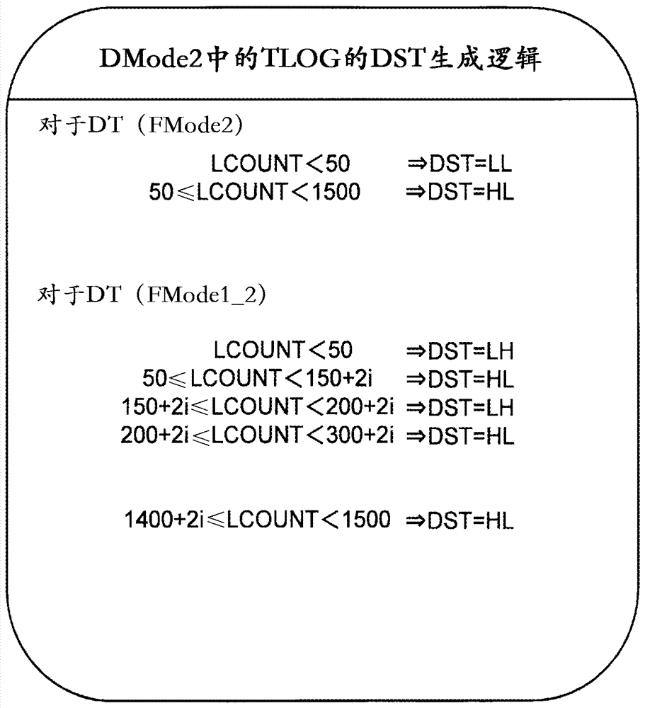
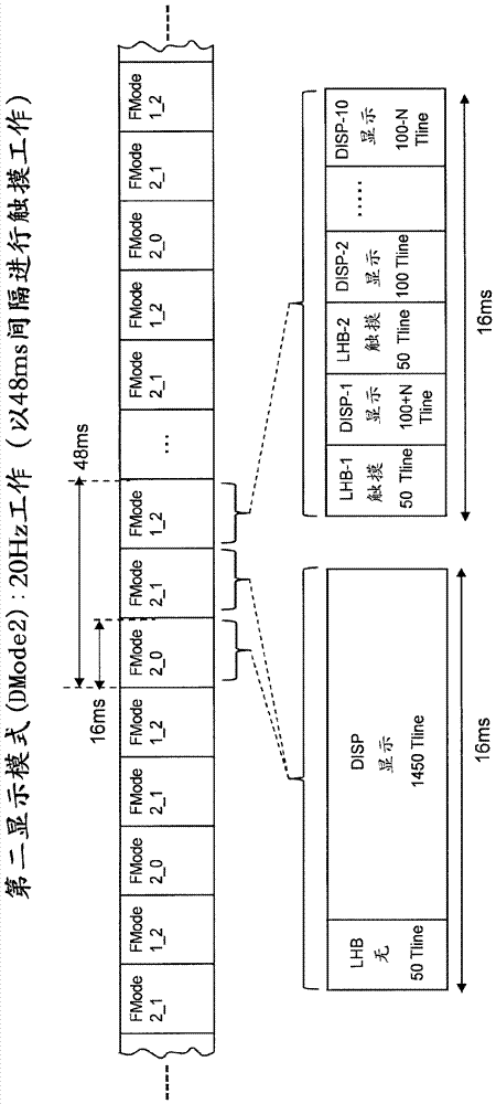
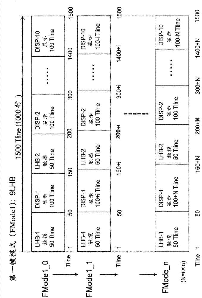
The present disclosure relates to a drive control device and electronic equipment, thereby totally simplifying the control of non-display and display drive terms in each display frame period, which a drive control device performs for the purpose of preventing display lines subjected to the degradation in display performance from being localized, or display lines with flicker arising thereon from being unevenly distributed in adopting the control arranged. Start timing of the display drive term and start timing of the non-display drive term are changed for each display frame period in a first frame mode. A second frame mode has a display drive term, and the display drive term is not interrupted by a non-display drive term halfway. The second frame mode is arranged so that the cycle of the display line clock signal in synchronization with the display line switching cycle is made longer than that in the first frame mode.

Description

technical field [0001] The present invention relates to a drive control device for driving and controlling a panel module for display and touch detection, furthermore, to an electronic device in which the drive control device is mounted on a panel module, and to a device for improving portable information terminals such as tablet computers and smart phones. Applied and effective technology for display quality of devices. Background technique [0002] On the surface of portable information terminal devices such as tablet PCs and smartphones, a panel module in which a display panel and a touch panel are overlapped or integrally formed is disposed, and the surface of the touch panel is touched with a finger or the like based on the screen display on the display panel. , the operation can be identified according to its touch coordinates. Currently, capacitive touch panels are widely used, and touch and non-touch are distinguished based on changes and differences in detection si...

Claims


Application Information

Patent Timeline
Patent Type & Authority Applications(China)
IPC IPC(8): G06F3/041G09G5/00
CPCG06F3/0412G06F3/0416G06F3/0418G09G5/006G09G3/3648G09G2354/00G09G2310/08G06F3/0446G06F3/04184G09G3/3677G09G2310/0202G09G2360/12G09G2360/18G06F3/043
Inventor 黑岩刚史能登隆行高梨光教
Owner OMNIVISION TDDI ONTARIO LLP
Learn More