
Displacement bodies in vehicle transmissions

A technology of transmission housing and displacement body, applied in the direction of gear lubrication/cooling, belt/chain/gear, transmission parts, etc., can solve the problems of leaving supply, shortage, etc., and achieve the effect of avoiding premature failure

Active Publication Date: 2021-08-24
ZF FRIEDRICHSHAFEN AG
View PDF2 Cites 0 Cited by
  • Summary
  • Abstract
  • Description
  • Claims
  • Application Information

AI Technical Summary

Problems solved by technology

In this case, the suction hole of the lubricant pump or part of the gear set will also leave lubricant and be undersupplied

Method used


Image

  • Displacement bodies in vehicle transmissions
  • Displacement bodies in vehicle transmissions
  • Displacement bodies in vehicle transmissions

Examples


Embodiment Construction

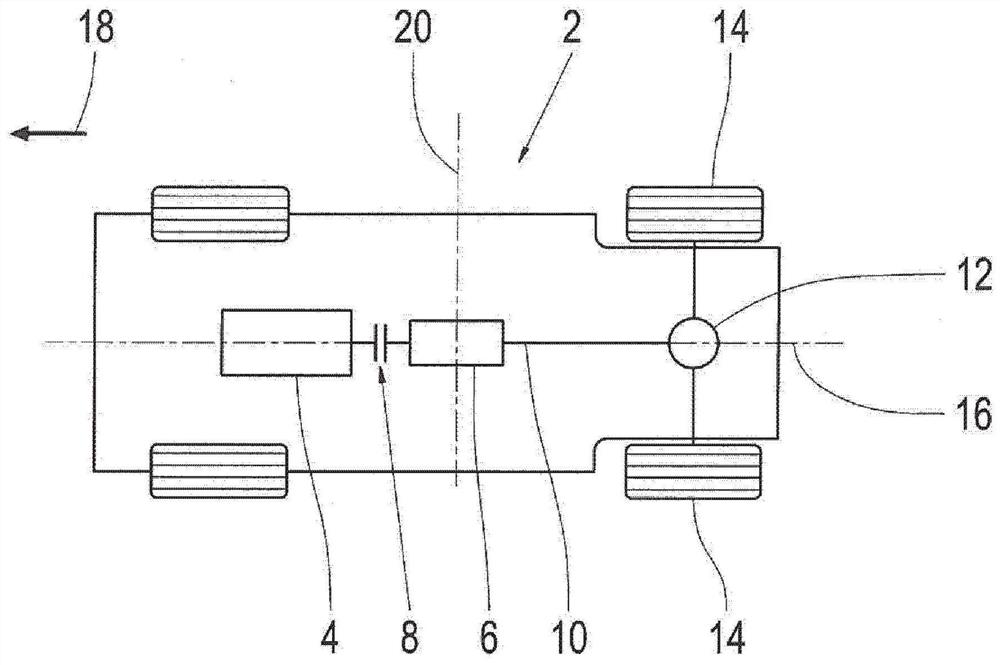
[0033] figure 1 A schematic vehicle diagram of a motor vehicle 2 is shown, which has a drive motor 4 , a transmission 6 and a clutch 8 arranged between the drive motor 4 and the transmission 6 . The transmission 6 is connected to the two rear wheels 14 via a drive shaft 10 and a differential 12 . A center axis 16 runs through the transmission, a center axis 16 runs in the direction of travel 18 of the motor vehicle 2 , and a center axis 20 runs transversely to the direction of travel 18 .

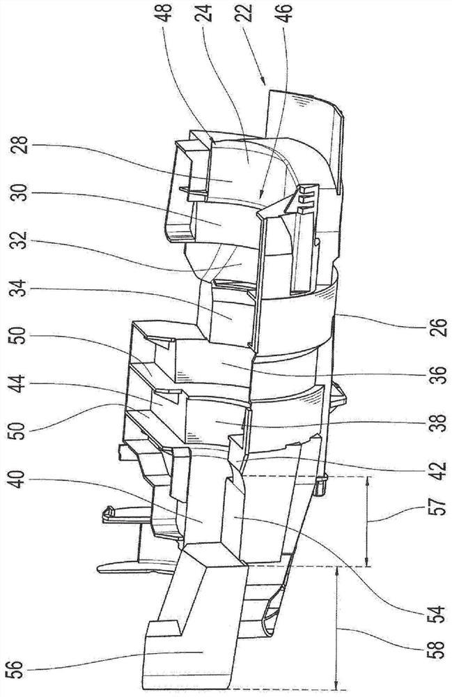
[0034] figure 2 Shown is a lubricant guide cup 22 in which a surface region 24 oriented in the direction of a rotating component accommodated in the lubricant guide cup and not shown here and a surface area 24 facing the surroundings and likewise not shown here are shown. The direction-oriented surface area 26 of the transmission housing. The surface area 24 oriented in the direction of the rotating component is divided into a plurality of sections 28 , 30 , 32 , 34 , 36 , 38 , 40 . Th...


PUM


Abstract

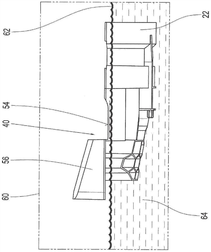
A displacement body in a vehicle transmission. A transmission (6) of a vehicle having a transmission housing (60) in which a lubricant reservoir (64) and a displacer (56) suitable for enlarging the fluid contained in the transmission housing (60) are provided The space occupied by the lubricant. The immersion of the displacement body ( 56 ) into the lubricant reservoir ( 64 ) is dependent on the driving state of the vehicle, so that in the first driving state the displacement body ( 56 ) is not immersed in the lubricant and thus allows the lubricant to reach the transmission First surface liquid level (62) in the housing. In a second driving state different from the first driving state, the displacement body (56) is immersed in the lubricant and thus causes the lubricant to occupy a second surface level (66) at least in parts of the transmission housing, wherein the The value of the second surface level (66) is greater than the value of the first surface level (62).

Description

technical field [0001] The invention relates to a vehicle transmission having a displacement body and a lubricant guide cup in a vehicle transmission having such a displacement body. Background technique [0002] In the transmission housing of a vehicle transmission, in addition to the devices required for carrying out the shifting process and the gear combinations of the individual transmission stages involved in the torque transmission between the drive side and the driven side, a certain amount of lubricant is stored , the gear combination and the devices used to implement the shifting process are used for cooling and lubrication. Oil or oil with additives is used as lubricant in most cases. [0003] In the transmission housing, the lubricant is substantially equalized and the surface formed by the lubricant occupies an evenly distributed fluid level during driving of a vehicle provided with the vehicle transmission on a level roadway. In this driving state, all gear co...

Claims


Application Information

Patent Timeline
Patent Type & Authority Patents(China)
IPC IPC(8): F16H57/04
CPCF16H57/042F16H57/0409F16H57/0423F16H57/0443F16H57/0447
Inventor 斯特凡·克雷默乔纳斯·帕尔特萨沙·菲泽尔
Owner ZF FRIEDRICHSHAFEN AG
Learn More