Toilet sewage discharge device
A sewage device and toilet technology, applied in the field of sanitary ware, can solve problems such as hidden water leakage and poor structural reliability
- Summary
- Abstract
- Description
- Claims
- Application Information
AI Technical Summary
Problems solved by technology
Method used
Image

Examples
Embodiment 1
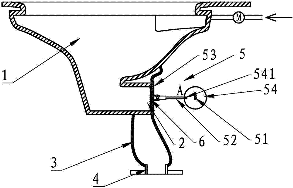
[0035] Such as figure 1 and figure 2 As shown, a toilet sewage discharge device includes a toilet seat 1 with a pelvic cavity. The bottom of the toilet seat 1 has a horizontally arranged sewage outlet 2, and an elastic water guide 3 is provided on the outside of the sewage outlet 2. The bottom of 1 is fixedly connected and communicated with the sewage outlet 2 and the sewage pipe 4, and the outer side of the elastic water guide 3 has an electric water sealing device 5.
[0036] Specifically, the electric water sealing device 5 includes a drainage motor 51 , a connecting rod 52 and a pressing plate 53 . Wherein, the output end of the drainage motor 51 is provided with a turntable 54, and the edge of the turntable 54 is provided with a traction shaft 541, and one end of the connecting rod 52 is provided with a sleeve which is sleeved on the traction shaft 541 and can make the connecting rod 52 rotate freely relative to the traction shaft 541. Connect the hole 521, and the oth...
Embodiment 2
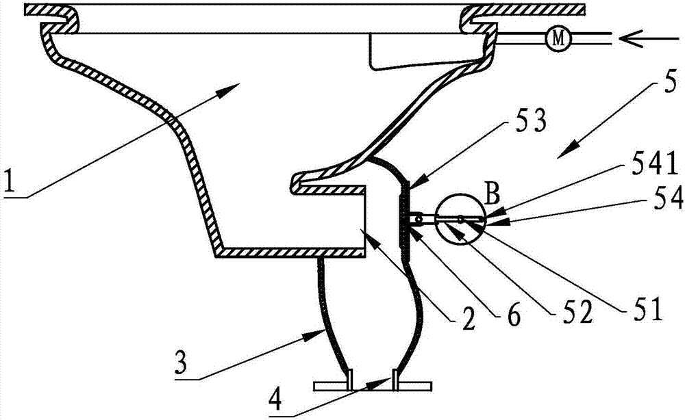
[0041] Such as image 3 and Figure 4 As shown, the difference from Embodiment 1 is that the electric water sealing device 5 of this embodiment includes a drainage motor 51 , a gear 55 , a connecting rod 52A with a rack 501 and a pressing plate 53 . Wherein, the gear 55 is arranged at the output end of the drainage motor 51 , and one end of the connecting rod 52A is connected to the pressing plate 53 , and the other end is connected with the drainage motor 51 through the gear rack 501 and the gear 55 .
[0042] In this embodiment, the elastic water guiding part 3 is a whole, and there is no need for sealing with the electric water sealing device 5, and the elastic water guiding part 3 and the toilet seat 1 are bonded and there is no relative movement, so the whole device does not involve dynamic sealing .
[0043] The working process of the above-mentioned structure is as follows, the drainage motor 51 rotates clockwise, drives the gear 55 to rotate, and the connecting rod 52A...
Embodiment 3
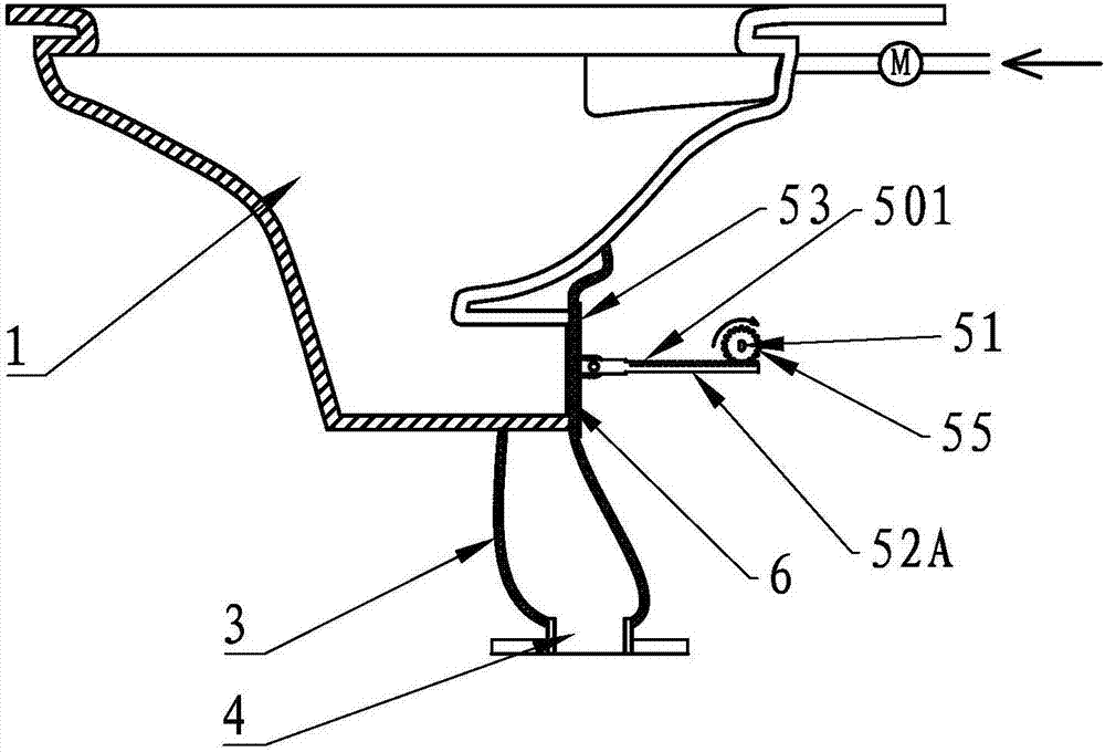
[0046] Such as Figure 5 and Figure 6 As shown, a toilet sewage discharge device includes a toilet seat 1 with a pelvic cavity. The bottom of the toilet seat 1 has a horizontally arranged sewage outlet 2. A rigid water guide 3A is provided on the outside of the sewage outlet 2. The rigid water guide 3A is connected to the sewage outlet. 2 and the sewage pipe 4, and the side wall of the rigid water guide 3A is provided with an electric water sealing device 5.
[0047] Specifically, the electric water sealing device 5 includes a drainage motor 51 , a connecting rod 52 , a bellows 56 , a guide plate 6 , a sealing disc 57 and a pressing disc 53 . Wherein, the drainage motor 51 is arranged on the outside of the rigid water diversion member 3A, and the output end of the drainage motor 51 is provided with a turntable 54, the rigid water diversion member 3A is provided with a through hole 30, and the edge of the turntable 54 is provided with a traction shaft 541, connecting rod 52 ...
PUM
 Abstract
Description
Claims
Application Information
 - Generate Ideas
- Intellectual Property
- Life Sciences
- Materials
- Tech Scout
- Unparalleled Data Quality
- Higher Quality Content
- 60% Fewer Hallucinations
Browse by: Latest US Patents, China's latest patents, Technical Efficacy Thesaurus, Application Domain, Technology Topic, Popular Technical Reports.
© 2025 PatSnap. All rights reserved.Legal|Privacy policy|Modern Slavery Act Transparency Statement|Sitemap|About US| Contact US: help@patsnap.com