Concealed flood control system
A hidden, tank-based technology, applied in dikes, sea area engineering, construction, etc., can solve problems such as poor waterproof performance, heavy workload, and difficult operations, so as to prevent water seepage, improve the ability to withstand flood impacts, and prevent seepage effect
- Summary
- Abstract
- Description
- Claims
- Application Information
AI Technical Summary
Problems solved by technology
Method used
Image
Examples
Embodiment 1
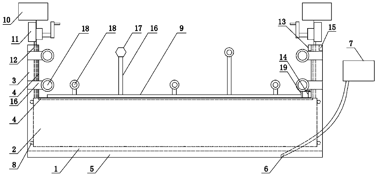
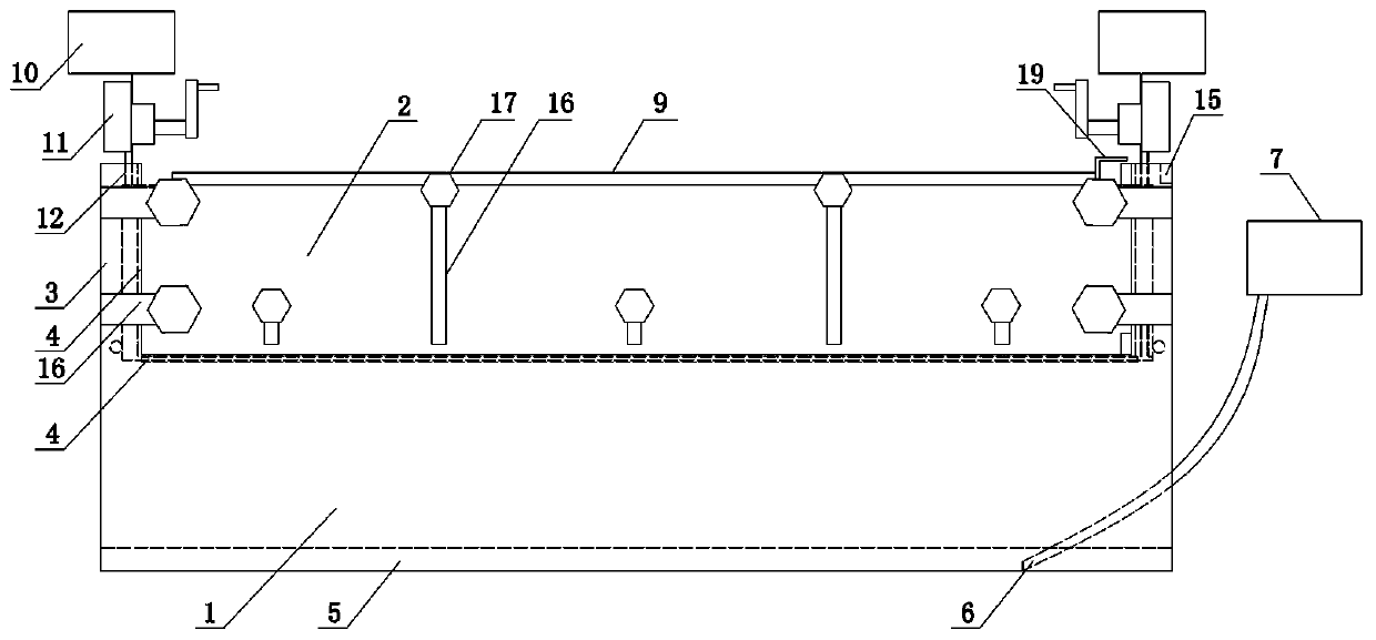
[0032] Such as figure 1 with figure 2 As shown, the present invention includes a main tank body 1, a water retaining plate 2, a power system and an auxiliary support structure, wherein guide rails 3 are arranged on the left and right sides of the main tank body 1, and bolts are passed through the notch of the main tank body 1 and the guide rails 3 The sealing gasket 4 is fixedly connected, and the drainage groove 5 is arranged under the main tank body 1, and the drainage groove 5 is connected with the main tank body 1, and the suction pipe 6 is arranged in the drainage groove 5, and the suction pipe 6 is connected with a water pump 7 and a water retaining plate 2 Located in the main tank body 1, guide wheels 8 matching the guide rail 3 are installed on the left and right sides of the water retaining plate 2, and the upper end of the water retaining plate 2 is welded with a protective plate 9 in the horizontal direction, and the width of the protective plate 9 is larger than t...
Embodiment 2
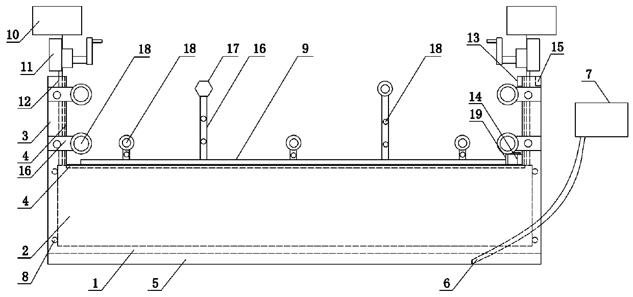
[0037]The present invention includes a main tank body 1, a water retaining plate 2, a power system and an auxiliary support structure, wherein guide rails 3 are arranged on the left and right sides of the main tank body 1, and the notch of the main tank body 1 and the inside of the guide rail 3 are fixedly connected and sealed by bolts Pad 4, a drain tank 5 is set under the main tank body 1, a water pump 6 is arranged in the drain tank 5, and the water pump 6 is connected to a water pump 7, the water retaining plate 2 is located in the main tank body 1, and the inner end surface of the water retaining plate 2 A plurality of rotating structures are arranged vertically. The rotating structure includes a rotating shaft and a rotating plate fixedly connected to the rotating shaft. The wheel 8 and the upper end of the water retaining plate 2 are welded with a protective plate 9 in the horizontal direction, and the width of the protective plate 9 is greater than the width of the notc...
Embodiment 3
[0041] The structure of this embodiment is basically the same as that of Embodiment 1, the difference is: as Figure 4 As shown, a plurality of buffer springs 22 are arranged in the drainage tank 5, and when the water retaining plate 2 falls into the main tank body 1, it contacts with the buffer springs 22. This structure effectively reduces the pulling force of the protective plate 9 and the traction rope 12, especially In the case of failure of the traction rope 12, the buffer spring 22 can effectively prevent the parts of the present invention from being damaged by the impact force when the water retaining plate 2 is in free fall.
PUM
 Abstract
Description
Claims
Application Information
 - R&D
- Intellectual Property
- Life Sciences
- Materials
- Tech Scout
- Unparalleled Data Quality
- Higher Quality Content
- 60% Fewer Hallucinations
Browse by: Latest US Patents, China's latest patents, Technical Efficacy Thesaurus, Application Domain, Technology Topic, Popular Technical Reports.
© 2025 PatSnap. All rights reserved.Legal|Privacy policy|Modern Slavery Act Transparency Statement|Sitemap|About US| Contact US: help@patsnap.com


