
Binocular camera

A technology of binocular camera and optical axis, which is applied in the direction of TV, color TV parts, electrical components, etc., to achieve the effect of increasing the field of view, increasing the overlapping area, and reducing the distance of blind spots

Inactive Publication Date: 2017-11-07
UISEE TECH BEIJING LTD
View PDF3 Cites 11 Cited by
  • Summary
  • Abstract
  • Description
  • Claims
  • Application Information

AI Technical Summary

Problems solved by technology

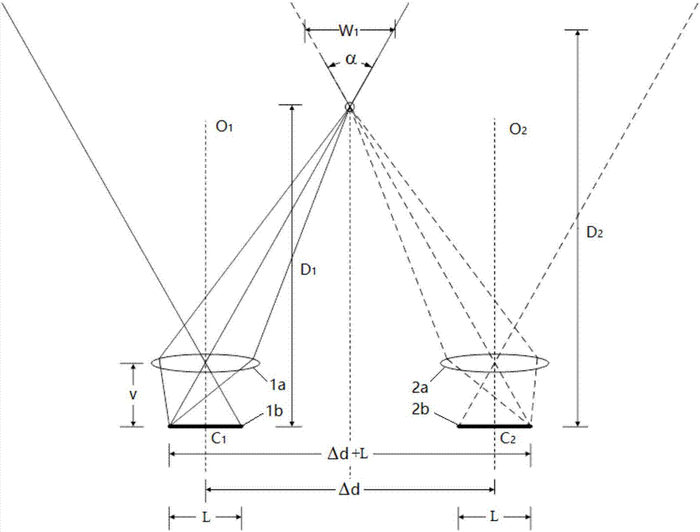
One problem is that the fields of view of the two lenses of the binocular camera overlap with each other after a certain distance D from the lens in the direction of the optical axis, and the binocular camera can only use the binocular parallax to stay away from Detect the three-dimensional space position of the object, so the area within the above distance D is the stereo vision detection blind area of ​​the binocular camera

Method used


Image

  • Binocular camera
  • Binocular camera
  • Binocular camera

Examples


Embodiment Construction

[0021] The application will be further described in detail below in conjunction with the accompanying drawings and embodiments. It should be understood that the specific embodiments described here are only used to explain related inventions, rather than to limit the invention. For ease of description, only parts related to the invention are shown in the drawings.

[0022] It should be noted that, in the case of no conflict, the embodiments in the present application and the features in the embodiments can be combined with each other. The present application will be described in detail below with reference to the accompanying drawings and embodiments.

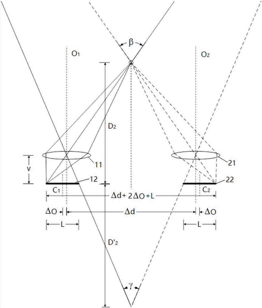
[0023] First, refer to figure 2 The arrangement of the imaging lens and the image sensor of the binocular camera according to the embodiment of the present invention will be described. The binocular camera includes a first imaging lens 11 and a second imaging lens 21 arranged side by side, and a first image sensor 12 and a s...


PUM


Abstract

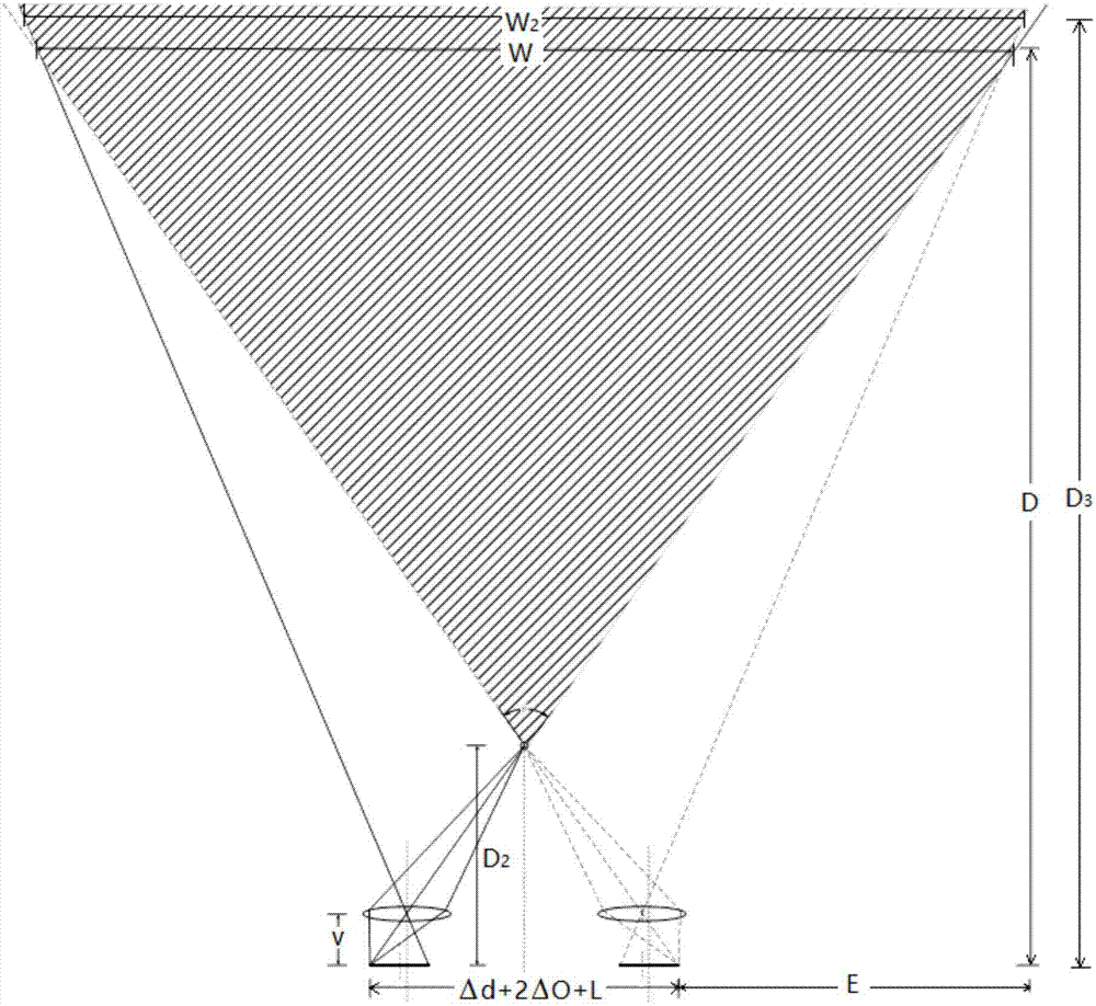
The invention discloses a binocular camera. The binocular camera comprises a first imaging lens, a second imaging lens, a first image sensor and a second image sensor; the first imaging lens and the second imaging lens are arranged side by side, and each provided with a first optical axis and a second optical axis; and the first image sensor and the second image sensor are respectively used for sensing images obtained by imaging of the first imaging lens and the second imaging lens, wherein the centres of the sensing surfaces of the first and second image sensors have the offset corresponding to the optical axis of the first and second imaging lens. The invention further discloses the binocular camera; and the binocular camera comprises a driving device used for driving the image sensors to move between the first position where the sensing surface of the image sensor is centred corresponding to the optical axis and the second position where the sensing surface has the offset corresponding to the optical axis. According to the binocular camera disclosed by the invention, the sensing surface of the image sensor offsets corresponding to the optical axis of the imaging lens, so that the view field overlapping area of the two imaging lenses can be adjusted according to different requirements.

Description

technical field [0001] The present invention generally relates to a stereo camera device, in particular to a binocular camera. Background technique [0002] Binocular cameras are an increasingly attractive device capable of providing stereoscopic vision. Based on the images obtained by the binocular camera, the three-dimensional space position of the object captured by the binocular camera relative to the camera can be calculated through the principle of binocular parallax. [0003] In a binocular camera, two imaging lenses usually have optical axes parallel to each other, and there is a certain distance between the lenses and the two image sensors. Since the two lenses have different viewing angles for the same imaged object, different images are obtained on the image sensor. The difference between the different images can then be used to calculate the distance of the object from the sensor. [0004] The sensing surface of an image sensor is usually smaller than the imag...

Claims


Application Information

Patent Timeline
Patent Type & Authority Applications(China)
IPC IPC(8): H04N5/225H04N5/232H04N13/02
CPCH04N13/239H04N23/45H04N23/54H04N23/60
Inventor 游宇
Owner UISEE TECH BEIJING LTD
Learn More