
Ultrasonic ranging system based on single-chip microcomputer

A distance measuring system and ultrasonic technology, which are applied in radio wave measurement systems, sound wave re-radiation, measurement devices, etc. The effect of exciting oscillation, reducing blind zone distance and improving accuracy

Inactive Publication Date: 2016-06-08
EASTERN LIAONING UNIV
View PDF5 Cites 3 Cited by
  • Summary
  • Abstract
  • Description
  • Claims
  • Application Information

AI Technical Summary

Problems solved by technology

[0003] The traditional ultrasonic return signal detection circuit is directly connected to both ends of the ultrasonic probe, which will bring disadvantages. First, the pulse signal that excites the ultrasonic probe will also enter the return signal detection circuit, which will easily cause the gain of the signal amplifier circuit to overflow, which will cause The amplifier circuit works self-oscillating, and the oscillation time is generally above 5mS. Therefore, during this period of time, the ultrasonic probe cannot detect the return signal of the obstacle due to the self-oscillating oscillation of the amplifier circuit, so it cannot measure the distance of the obstacle. The so-called ultrasonic blind zone, the best known ultrasonic probe can generally control the self-excited oscillation time at 3.5mS, and the corresponding blind zone distance is about 60cm, which greatly limits the application of ultrasonic in short-distance detection
[0004] At the same time, different ambient temperatures, air quality, and sound speed all have a great influence on the ultrasonic distance measurement results, and the ultrasonic distance measurement systems in the prior art do not consider the above factors, so the error is relatively large

Method used


Image

  • Ultrasonic ranging system based on single-chip microcomputer

Examples


Embodiment Construction

[0022] In order to make the objects and advantages of the present invention clearer, the present invention will be further described in detail below in conjunction with the examples. It should be understood that the specific embodiments described here are only used to explain the present invention, not to limit the present invention.

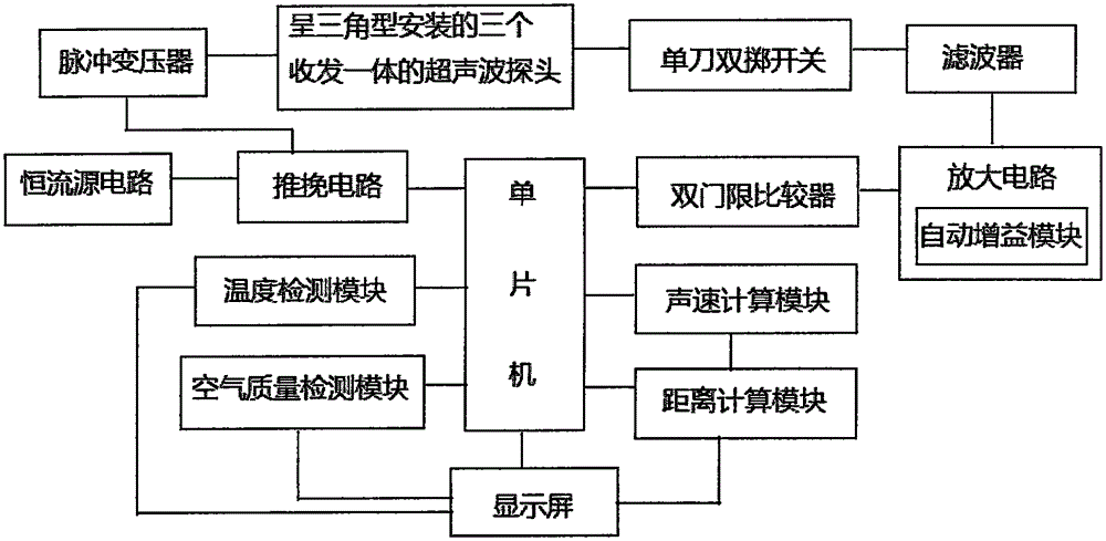
[0023] Such as figure 1 As shown, the embodiment of the present invention provides an ultrasonic ranging system based on a single-chip microcomputer, including several ultrasonic probes integrated with transceivers, a drive circuit, a return signal detection circuit and a single-chip microcomputer, the start signal output end of the single-chip microcomputer is connected to the drive circuit, and the output of the drive circuit end is connected to the ultrasonic probe, and the detection signal of the ultrasonic probe is output to the return signal detection circuit, and the output end of the return signal detection circuit is connected to the si...


PUM


Abstract

The invention discloses an ultrasonic ranging system based on a single-chip microcomputer. The ultrasonic ranging system comprises three transmitting-receiving integrated ultrasonic probes which are triangularly installed. A single-pole double-throw switch is arranged between the signal output end of the ultrasonic probes and a return signal detecting circuit. When the single-chip microcomputer transmits a starting signal to a driving circuit, the single-pole double-throw switch is switched off for realizing disconnection with the return signal detecting circuit in the ultrasonic ranging system. When the single-chip microcomputer stops transmission of the starting signal to the driving circuit, the single-pole double-throw switch is switched on for realizing connection with the return signal detecting circuit in the ultrasonic ranging system. The ultrasonic ranging system further comprises a temperature detecting module, an air quality detecting module, a sound speed calculating module and a range calculating module. The ultrasonic ranging system has advantages of reducing or restraining self-excited oscillation of an ultrasonic wave signal amplification circuit, reducing blind area distance in ultrasonic ranging, extending application of ultrasonic wave in short-distance measurement and furthermore realizing high detection precision.

Description

technical field [0001] The invention relates to the field of ultrasonic ranging, in particular to an ultrasonic ranging system based on a single-chip microcomputer. Background technique [0002] With the development of science and technology, people are becoming more and more aware of the characteristics of ultrasonic waves, and the wide application of ultrasonic waves has brought a lot of convenience to our lives. Due to the strong directivity of ultrasonic waves, it is often used for distance measurement, and its measurement accuracy can reach millimeter level, so it basically meets the daily use. At present, it has been widely used in automobile safety, such as front and rear reversing radar ranging, blind spot detection system, etc. . [0003] The traditional ultrasonic return signal detection circuit is directly connected to both ends of the ultrasonic probe, which will bring disadvantages. First, the pulse signal that excites the ultrasonic probe will also enter the r...

Claims


Application Information

Patent Timeline
Patent Type & Authority Applications(China)
IPC IPC(8): G01S15/08G01S15/93
CPCG01S15/08G01S15/931
Inventor 周春明赵娜
Owner EASTERN LIAONING UNIV
Learn More