
A stator clapping machine

A press and stator technology, which is applied in the manufacture of stator/rotor bodies, etc., can solve problems such as affecting the efficiency of stator beat pressure, and achieve the effect of improving safety.

Active Publication Date: 2019-11-26
邳州市城洁保洁有限公司
View PDF5 Cites 0 Cited by
  • Summary
  • Abstract
  • Description
  • Claims
  • Application Information

AI Technical Summary

Problems solved by technology

[0004] The technical problem to be solved by the present invention is: to provide a stator clap press machine, which solves the problem that the existing stator clap press machine requires the operator to place the stator core on the base or move the heavy stator core many times when it is removed. Stator beat pressure efficiency problem

Method used


Image

  • A stator clapping machine

Examples


Embodiment 1

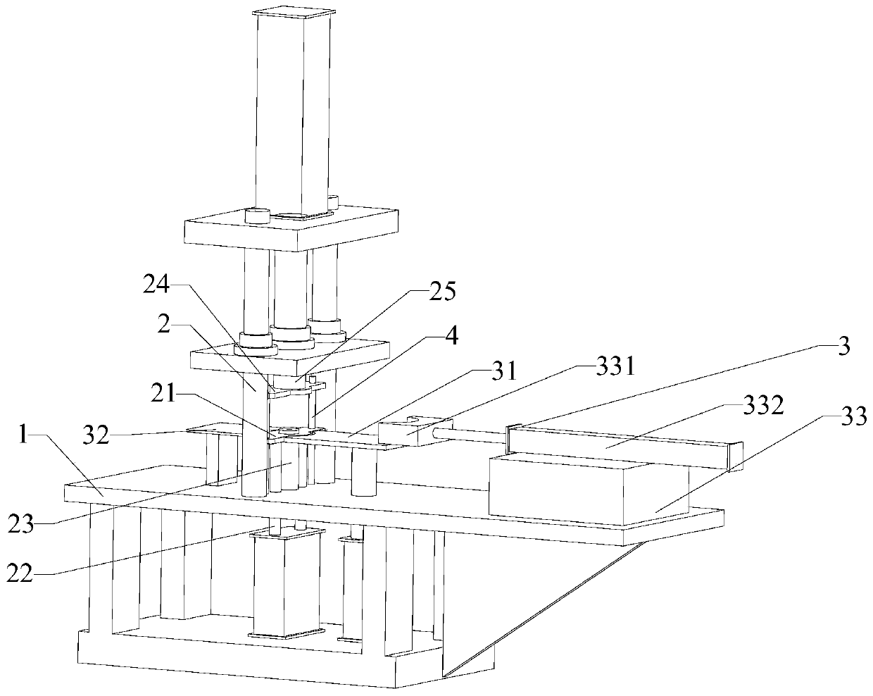
[0064] A stator slapping machine, comprising a base 1, a slapping mechanism 2, a delivery mechanism 3 and a servo driver; the slapping mechanism 2 and the delivery mechanism 3 are connected to the base 1; the slapping mechanism 2 includes a base 21 , the base 21 lifting cylinder, the limit block 23 and the hydraulic clapping mechanism 2; the limit block 23 is a cylinder with the same diameter as the inner diameter of the stator core; the axial direction of the limit block 23 is vertical direction; the edge of the upper surface of the limit block 23 is provided with chamfers; Move in a straight direction; the hydraulic clapping mechanism 2 includes a pressure block 24 and an oil pressure rod 25 connected to the top of the pressure block 24, the pressure block 24 is a ring cylinder whose inner diameter is the same as that of the limit block 23, The briquetting block 24 moves vertically under the action of the oil pressure rod 25; the conveying mechanism 3 includes a feeding plat...

Embodiment 2

[0066] A stator slapping machine, the distance between the feeding platform and the base 21 is 5 mm; the distance between the discharging platform 32 and the base 21 is 5 mm; other features are the same as those in Embodiment 1.

Embodiment 3

[0068] A stator slapping machine, the distance between the feeding platform and the base 21 is 10 mm; the distance between the discharging platform 32 and the base 21 is 10 mm; other features are the same as those in Embodiment 1.

[0069] To sum up, the base of the stator cladding machine provided by the present invention is designed as a liftable base. When the stator core to be clapped needs to be placed on the base or the stator core needs to be removed after stamping, the base is lifted on the base. Driven by the cylinder, it moves to the same plane as the upper surface of the limit block, the feeding platform and the discharging platform, so that the feeding or unloading of the stator core can be automatically completed through the pusher, and the stator core is directly connected to the stator core without manual work. The limit block of the base avoids the risk of the operator's hands being crushed. While the stator slapping machine is slapping, the operator can place t...


PUM


Abstract

The invention relates to a stator clapping and pressing machine which comprises a pedestal, a clapping and pressing mechanism, a conveying mechanism and a servo driver, wherein the clapping and pressing mechanism and the conveying mechanism are connected on the pedestal, and the clapping and pressing mechanism comprises a pedestal, a pedestal lifting cylinder, a stopper and an oil pressure clapping and pressing mechanism. The pedestal under the effect of pedestal lifting cylinder moves vertically. The oil pressure clapping and pressing mechanism comprises a pressing block and an oil pressure bar connected to the upper portion of the pressing block, and the pressing block under the effect of an oil pressure rod moves vertically. The conveying mechanism comprises a feeding platform, a discharging platform and a pushing handle mechanism. The pedestal when driven by the pedestal lifting cylinder moves to form a same plane with the upper surface of the stopper, the charging platform and a discharging platform, so that charging and discharging of stator cores can be automatically completed through the pushing handle. The stator clapping and pressing efficiency and safety can be improved.

Description

technical field [0001] The invention relates to the field of motor production and manufacturing, in particular to a stator clapping machine. Background technique [0002] The motor stator in the prior art is stamped by a high-speed punching die of silicon steel sheets. Since the self-fastening point of the stator silicon steel sheets cannot be punched very tightly, after the stator silicon steel sheets are preliminarily laminated into a stator core, it is necessary to use a beater. Pressing machine for flattening and compacting; [0003] The existing pressing machine needs to manually place the preliminary laminated stator core on the base of the pressing machine, and the stator core on the base is flattened and compacted by the hydraulic press above. After the pressing is completed, manual labor is required. Remove the stator core on the base, and then place the next stator core to be pressed on the base, and continue to press; since the stator core is similar to a circula...

Claims


Application Information

Patent Timeline
Patent Type & Authority Patents(China)
IPC IPC(8): H02K15/02
CPCH02K15/02
Inventor 郑锦锋张小波林清
Owner 邳州市城洁保洁有限公司
Learn More