Motor power commutator

A technology of motor power supply and commutator, applied in the direction of electromechanical devices, electrical components, electric components, etc., can solve the problems of high labor cost and low efficiency, and achieve the effect of simplifying the wiring method of wires

Pending Publication Date: 2017-11-07
温州市圣帕电子科技有限公司 +1
View PDF0 Cites 0 Cited by
  • Summary
  • Abstract
  • Description
  • Claims
  • Application Information

AI Technical Summary

Problems solved by technology

Therefore, the traditional forward and reverse switches have the disadvantages of low efficiency and high labor cost in terms of production process and wiring method

Method used


Image

  • Motor power commutator
  • Motor power commutator
  • Motor power commutator

Examples


Embodiment 1

[0038] Embodiment 1: Wiring mode of remote control motor and motor power commutator

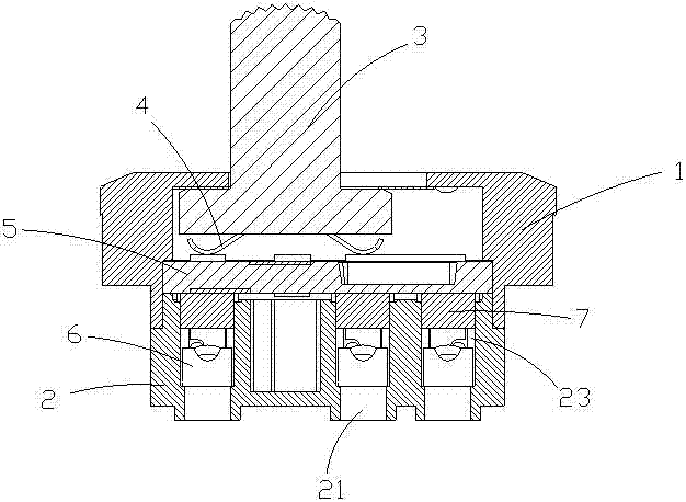
[0039] The negative end of the power supply is connected to the starting capacitor through the first connector, and the first connector is connected to any one of the second connecting pin 52 and the third connecting pin 53 through wires, and the motor The red wire is connected to the starting capacitor, the positive end of the power supply is connected to the gray wire of the motor through the second connector, and the second connector is connected to any of the fifth connecting pin 55 and the sixth connecting pin 56 through a wire. One connection pin, the orange wire of the motor is connected to the first connection pin 51 , and the yellow wire of the motor is connected to the fourth connection pin 54 .

Embodiment 2

[0040] Embodiment 2: Wiring mode of pull-speed motor and motor power commutator

[0041] The input terminal of the pull-speed switch is connected to the positive terminal of the power supply through wires, the output end of the pull-speed switch and the red wire of the motor are both connected to the start capacitor through wires, and the start capacitor is connected to the second connection pin 52 and the third connection lead through wires. Any one connection pin in the two pins 53, the negative end of the power supply and the gray wire of the motor are connected to the third connector through wires, and the third connector is connected to the fifth connection pin 55 and the sixth connection pin through wires. Any one of the two wiring pins of the pin 56, the orange wire of the motor is connected to the first wiring pin 51, and the yellow wire of the motor is connected to the fourth wiring pin 54.


PUM


Abstract

The invention discloses a motor power commutator which comprises an upper cover, a pedestal, a poking handle, reeds and a deflector. A first wiring pin and a second contact are connected through a first conducting sheet, and a fourth wiring pin and a first contact are connected through a second conducting sheet. The pedestal is provided with wiring holes corresponding to each wiring pin of the deflector, the deflector is placed on the pedestal, and each wiring pin of the deflector is positioned in corresponding wiring hole. Two reeds are correspondingly arranged on the lower portion of the poking handle, the reeds on the lower portion of the poking handle are contacted with the wiring pins on the upper portion of the deflector. The poking handle and the deflector are installed on the pedestal in a tightly pressing manner through the upper cover, and the upper end of the poking handle penetrates through and projects out of the top of the upper cover. The motor power commutator satisfies the requirements of motor conjunction boxes of different specifications. The deflector employs a bi-layer structure. The current direction is changed by poking any of the two ends of the poking handle to realize clockwise and counter-clockwise rotation of a switch. The motor power commutator has rapid wire plugging and pushing function.

Description

Technical field: [0001] The invention belongs to the technical field of power steering control, and in particular relates to a commutator which simplifies the wiring mode of power supply and realizes electric phase conversion. Background technique: [0002] At present, the ceiling fan industry uses the traditional reversible switch to control the reversing direction of the fan. The wiring method requires a lot of labor and the production process is too cumbersome and may cause defective products. In terms of customer use, when assembling the traditional reversible switch, it is necessary to use terminals to connect the power coil outlet of the internal motor of the ceiling fan. In the traditional production process, it is necessary to operate tools to connect the terminal to the outlet seat of the reversible switch. Therefore, the traditional reversing switch has the disadvantages of low efficiency and high labor cost in terms of production process and wiring method. Inven...

Claims


Application Information

Patent Timeline
IPC IPC(8): H02K13/10H02K5/22
CPCH02K5/225H02K13/10
Inventor 陈建道
Owner 温州市圣帕电子科技有限公司
Why Eureka
Try Eureka