
An In-Situ Observation System for Dynamic Changes of Submarine Boundary Layer

An observation system and interface layer technology, which is applied in the direction of measuring devices, surveying and navigation, open-air water source survey, etc., can solve the problems that cannot realize the observation of multi-phase field interaction in the interface layer of the seabed, and achieve simple structure design and deployment operation , cost reduction effect

Active Publication Date: 2019-01-18
OCEAN UNIV OF CHINA
View PDF6 Cites 0 Cited by
  • Summary
  • Abstract
  • Description
  • Claims
  • Application Information

AI Technical Summary

Problems solved by technology

[0004] At present, the observation equipment on the seabed interface layer is limited to the observation of the hydrodynamic force above the seabed surface, the erosion deposition and resuspension of the seabed interface, and most of them can only realize the observation of the upper water body of the seabed interface, including the upper hydrodynamic force, suspension Sediment observations are still unable to simultaneously observe the multiphase field interaction of the seabed interface layer including seabed sediments, which has become an important factor restricting the study of the seabed interface layer

Method used


Image

  • An In-Situ Observation System for Dynamic Changes of Submarine Boundary Layer
  • An In-Situ Observation System for Dynamic Changes of Submarine Boundary Layer
  • An In-Situ Observation System for Dynamic Changes of Submarine Boundary Layer

Examples


Embodiment Construction

[0023] In order to understand the above-mentioned purpose, features and advantages of the present invention more clearly, the present invention will be further described below in conjunction with the accompanying drawings and embodiments.

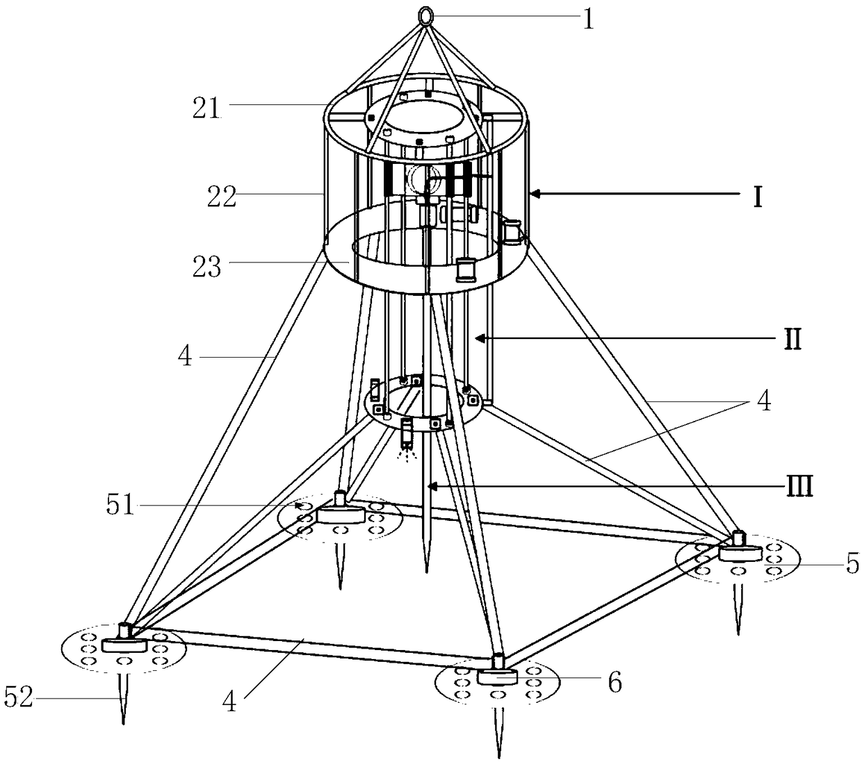
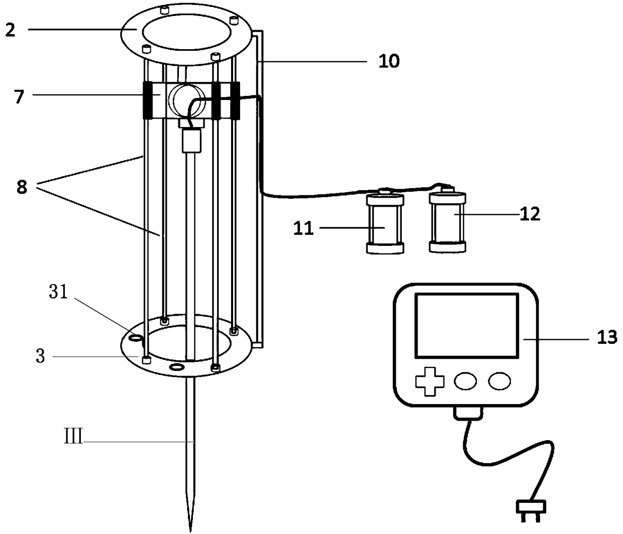
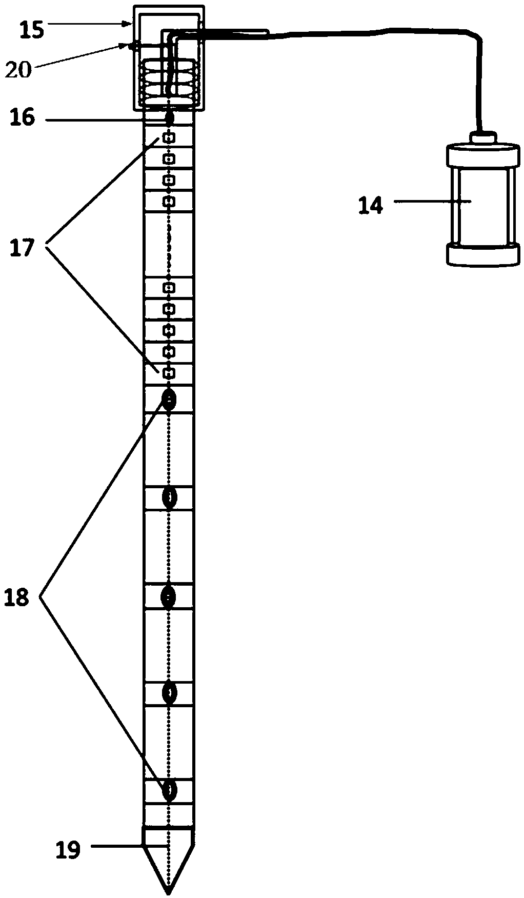
[0024] The in-situ observation system for the dynamic change of the seabed interface layer proposed in this example provides the necessary technical support for the study of the dynamic evolution of the seabed interface layer in the Yellow River delta. The observation system can realize the three-phase medium of ocean water body-seabed interface-seabed sediment The observation content includes the accumulation and dissipation process of sediment pore water pressure within 1.5m of the seabed sediment, the change of erosion and deposition at the seabed interface, and the suspended sediment in the water above the seabed interface, the seawater flow velocity and the temperature, salt and depth changes. Wait.

[0025] Specifically, refer to fig...


PUM


Abstract

The invention discloses a dynamic change original position observation system for a seabed interfacial layer. The dynamic change original position observation system comprises a seabed interfacial layer observation platform, an oscillating type detection rod penetrating apparatus and a multiparameter observation detection rod, wherein the seabed interfacial layer observation platform is used for loading various observation apparatuses and the oscillating type detection rod penetrating apparatus and is in riveted connection with the detection rod penetrating apparatus, the probe of an anti-sinking plate and a through hole are designed to form the laying stability and recovery convenience of an entire observation system, and the oscillating type detection rod penetrating apparatus uses a vibration exciter to generate vertical power to allow the observation detection rod to continuously insert in seabed deposit. New design principle and means are employed, partial liquefaction and strength reduction of seabed deposit can be realized through high frequency vibration, so that the observation detection rod can continuously insert in the seabed deposit, and the implementation is more convenient. The multiparameter observation detection rod is connected with the vibration exciter, and integrated with various sensors to realize synchronous observation of three-phase media of sea water body-seabed interface-seabed deposit. A water inlet fine pipe is provided and a water inlet when opened during recovery can eliminate vacuum suction on the bottom of the detection rod to facilitate recovery. The observation system provides essential technology support for researching dynamic evolution of the seabed interfacial layer.

Description

technical field [0001] The invention belongs to the technical field of ocean observation, and in particular relates to an in-situ observation system for the dynamic change of the seabed interface layer. Background technique [0002] The seabed interface layer is the area where the seabed sediments interact with the bottom seawater. The sediments in this layer will undergo complex dynamic responses, and its material composition and structural characteristics are hot issues of common concern in marine science and engineering. Through the in-situ long-term automatic observation of the dynamic change process of the seabed boundary layer, it is important to study the evolution law of the coastal zone, the formation mechanism of geological disasters, the sedimentation dynamics process, the structural characteristics and evolution conditions of the seabed boundary layer, and quantitatively determine the dynamic evolution law of the seabed boundary layer. significance. Long-term in...

Claims


Application Information

Patent Timeline
Patent Type & Authority Patents(China)
IPC IPC(8): G01M10/00G01C13/00G01D21/02
CPCG01C13/002G01D21/02G01M10/00
Inventor 贾永刚文明征刘晓磊张少同崔凯
Owner OCEAN UNIV OF CHINA
Learn More