
An anti-jamming z-axis balance device

A balancing device and anti-jamming technology, which is applied to metal processing equipment, metal processing machinery parts, manufacturing tools, etc., can solve problems such as jamming, different frictional changes, jamming, etc., to reduce processing accuracy and reduce Requirements for parallelism and the effect of reducing coaxiality

Active Publication Date: 2019-08-20
BOZHON PRECISION IND TECH CO LTD +1
View PDF7 Cites 0 Cited by
  • Summary
  • Abstract
  • Description
  • Claims
  • Application Information

AI Technical Summary

Problems solved by technology

[0002] With the development of economy and science and technology, the application of automation equipment in industrial production is becoming more and more extensive. In the technology of direct drive of linear motor, in actual use, it is found that due to the limitation of the machining accuracy of the upper and lower mounting plates of the cylinder, the single cylinder and the upper and lower When the mounting plate is installed, it is different from the shaft and the left and right cylinders are not parallel to each other and the guide rail. The light one will cause the friction force of the slider on different positions of the slide rail to be different and vary greatly, which will increase the difficulty of control. At the same time, it will also increase the geometric errors such as straightness and pitch angle of the motion unit on the Z-axis, which will have a serious impact on equipment that requires trajectory accuracy during high-precision motion; the most serious is because the cylinder and the guide rail are not parallel. , and the cylinder and the upper and lower mounting blocks are not in the same axis, causing the whole movement to be stuck and stuck

Method used


Image

  • An anti-jamming z-axis balance device
  • An anti-jamming z-axis balance device
  • An anti-jamming z-axis balance device

Examples


Embodiment Construction

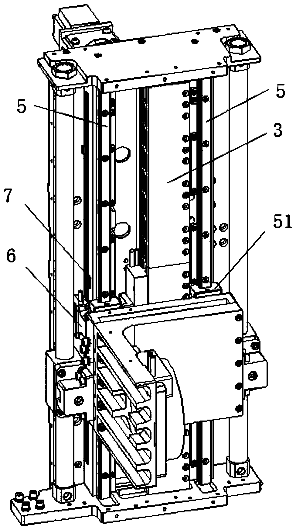
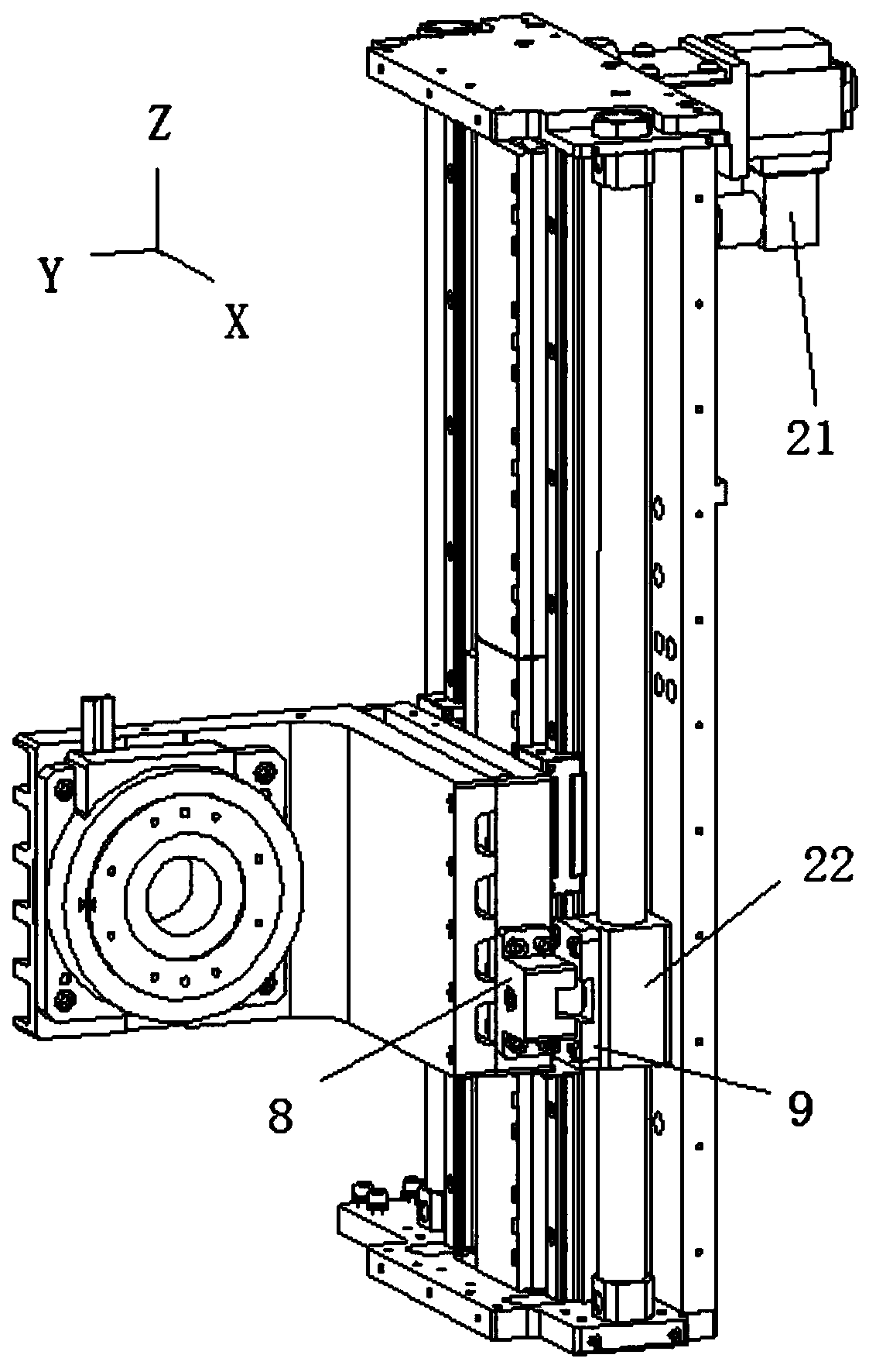
[0017] see Figure 1 to Figure 4 , an anti-jamming Z-axis balancing device, comprising a linear motor module 3, a Z-axis moving module 4 driven by the linear motor module 3, a slider 51 connected to the Z-axis moving module 4, and a sliding block engaged with the slider 51 Rail 5. There are two slide rails 5, and the two slide rails 5 are arranged in parallel and along the Z-axis direction, and the linear motor module 3 drives the Z-axis moving module 4 to move along the Z-axis.

[0018] The anti-jamming Z-axis balancing device also includes two rodless cylinder blocks 2 arranged in parallel, a rodless cylinder slider 22 installed on the rodless cylinder body 2, and a chute connected with the rodless cylinder slider 22 Part 9, the fixing part 8 connected with the Z-axis moving module 4, the fixing part 8 is connected with a sliding column 82, the fixing part 8 is provided with a fixing groove 81 for installing the sliding column 82, and the sliding column 82 is fixed with the...


PUM


Abstract

The invention relates to an anti-seizing Z-axis balancing device. The anti-seizing Z-axis balancing device comprises a Z-axis moving module, two non-rod air cylinder bodies, non-rod air cylinder slide blocks, sliding chute pieces and fixed pieces, wherein the two non-rod air cylinder bodies are arranged in parallel to each other, the non-rod air cylinder slide blocks are installed on the non-rod air cylinder bodies, the sliding chute pieces are connected with the non-rod air cylinder slide blocks, and the fixed pieces are connected with the Z-axis moving module; and the fixed pieces are connected with slide columns, sliding chutes are formed in the sliding chute pieces, the slide columns are located in the sliding chutes and slide in the X-axis direction, gaps exist between the slide columns and the sliding chutes in the Z-axis direction, and gaps exist between the fixed pieces and the sliding chute pieces in the Y-axis direction. According to the anti-seizing Z-axis balancing device, the machining precision of installed parts can be reduced, the coaxiality of air cylinders in the installing process can be reduced, the requirement for the parallelism degree between the air cylinders and slide rails can be reduced, and the anti-seizing function is achieved.

Description

technical field [0001] The invention relates to the field of automation equipment, in particular to an anti-jamming Z-axis balance device. Background technique [0002] With the development of economy and science and technology, the application of automation equipment in industrial production is becoming more and more extensive. In the technology of direct drive of linear motor, in actual use, it is found that due to the limitation of the machining accuracy of the upper and lower mounting plates of the cylinder, the single cylinder and the upper and lower When the mounting plate is installed, it is different from the shaft and the left and right cylinders are not parallel to each other and the guide rail. The light one will cause the friction force of the slider on different positions of the slide rail to be different and vary greatly, which will increase the difficulty of control. At the same time, it will also increase the geometric errors such as straightness and pitch an...

Claims


Application Information

Patent Timeline
Patent Type & Authority Patents(China)
IPC IPC(8): B23Q1/01B23Q1/26
Inventor 施志虎李朝军孟健陈良锋李向东于福祥丛周建史文浩史军新
Owner BOZHON PRECISION IND TECH CO LTD
Learn More