Distributed anti-clogging abdominal cavity hyperthermal perfusion drainage tube

An anti-clogging, hot perfusion technology, applied in catheters, suction and irrigation systems, suction devices, etc., can solve the problems of drainage tube disconnection, drainage tube blockage, non-conformity, etc., to prevent drainage tube clogging, smooth drainage, and avoid clogging. Effect

Active Publication Date: 2017-11-07
SHANDONG RES INST OF TUMOUR PREVENTION TREATMENT
View PDF5 Cites 2 Cited by
  • Summary
  • Abstract
  • Description
  • Claims
  • Application Information

AI Technical Summary

Problems solved by technology

However, placing multiple drainage tubes not only increases the pain, trauma and infection risk of patients, but also does not conform to the current minimally invasive concept
The second common risk is the blockage of the peritoneal hyperthermic perfusion tube: patients with hyperthermic perfusion are usually placed after surgery, but postoperative pelvic abdominal necrotic tissue b

Method used


Image

  • Distributed anti-clogging abdominal cavity hyperthermal perfusion drainage tube
  • Distributed anti-clogging abdominal cavity hyperthermal perfusion drainage tube
  • Distributed anti-clogging abdominal cavity hyperthermal perfusion drainage tube

Examples


Embodiment 1

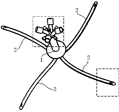
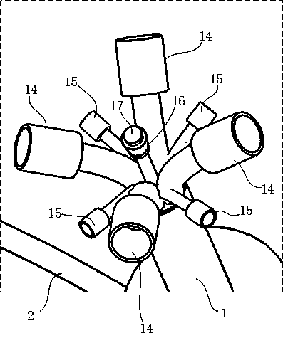
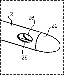
[0036]Embodiment 1, a decentralized anti-clogging peritoneal hyperthermic perfusion drainage tube, including a double-lumen catheter 2 placed on the left and right under the abdominal diaphragm, and a double-lumen catheter 2 on the left and right of the pelvic floor. The double-lumen catheter 2 has a drainage cavity 21, a flushing cavity 22, the end of the double-lumen catheter 2 is tapered and closed into a smooth bullet 24, and a flushing port 25 communicating with the branch flushing cavity 22 is opened on the bullet 24; The double-lumen catheter 2 is provided with two opposite drainage ports 26 communicating with the drainage chamber 21; it also includes a main catheter 1, and the upper ends of the four double-lumen catheters 2 and the lower end of the main pipe 1 are in the shape of a "cross" Distributed and connected as a whole, the main pipe 1 is provided with four main flushing chambers 11 uniformly distributed around its center of circle, four main drainage chambers 12...

Embodiment 2

[0041] Embodiment 2, others are the same as Embodiment 1, the difference is that the tube wall of the main pipe 1 includes the inner layer 202 that opens the main flushing chamber 11 and the main drainage chamber 12, and the latex that is combined with the inner layer 202 The outer layer 201, the center of the inner layer 202 is also provided with an inflatable chamber 13, and the upper end of the main pipe 1 is also provided with an inflatable joint 16 communicating with the inflatable chamber 13, and a self-sealing valve 17 is arranged in the inflatable joint 16. A section of latex inner layer 202' near the lower end of the main pipe 1 is not combined with a section of latex outer layer 201' but is separated from each other to form a gap. On this section of latex inner layer 202', a section communicating with the gas-filled cavity 13 and avoiding Open the air outlet chamber 17 of the main flushing chamber 11 and the main drainage chamber 12, and the air outlet chamber 17 is o...


PUM

PropertyMeasurementUnit
Outer diameteraaaaaaaaaa
Long trailaaaaaaaaaa

Abstract

The invention discloses a distributed anti-clogging abdominal cavity hyperthermal perfusion drainage tube. The upper ends of four dual-cavity catheters are always integrally connected with the lower end of a total tube in a cross shape, the total tube is internally provided with four main flushing cavities and four main drainage cavities, the lower ends of the four main flushing cavities are communicated with flushing cavities of four dual-cavity catheters respectively, and the lower ends of the four main drainage cavities are communicated with the drainage cavities of the four dual-cavity catheters respectively; four drainage connectors communicated with the main drainage cavities and four washing connectors communicated with the main flushing cavities are arranged at the upper end of the total tube. Compared with the prior art, the number of pipes which penetrate through the abdominal wall is the smallest, and the risk can be effectively avoided that discomfort is induced since the catheters are left in the body and stimulate the peritoneum and organs.

Description

technical field [0001] The invention relates to a medical device, in particular to a decentralized anti-clogging abdominal cavity heat perfusion drainage tube. Background technique [0002] For patients who are going to undergo hyperthermic perfusion of the abdominal cavity, it is generally necessary to place infusion tubes symmetrically up and down, left and right, to the subdiaphragm and pelvic floor after abdominal and pelvic surgery, so that the perfusion fluid can fill the peritoneal cavity. Generally, 4 catheters are placed. Multiple drainage tubes can effectively lavage the entire abdominal cavity and drain thoroughly. However, placing multiple drainage tubes not only increases the pain, trauma and infection risk of patients, but also does not conform to the current minimally invasive concept. The second common risk is the blockage of the peritoneal hyperthermic perfusion tube: patients with hyperthermic perfusion are usually placed after surgery, but postoperative p...

Claims


Application Information

Patent Timeline
IPC IPC(8): A61M1/00A61M3/02A61M25/14A61M31/00
CPCA61M1/0058A61M3/0283A61M25/0023A61M31/00A61M1/85Y02A50/30
Inventor 陈亮张方刘博文陈月婷
Owner SHANDONG RES INST OF TUMOUR PREVENTION TREATMENT
Why Eureka
Try Eureka