
Spinning winding mechanism capable of selecting control drive by itself

A technology of winding mechanism and driving cavity, which is applied in the direction of conveying filamentous materials, thin material processing, transportation and packaging, etc., which can solve the problems of low work efficiency, inconvenient use, waste of man-hours, etc., to improve efficiency and improve work Efficiency, the effect of reducing procurement costs

Inactive Publication Date: 2017-11-03
桐乡市建泰纺织有限公司
View PDF6 Cites 0 Cited by
  • Summary
  • Abstract
  • Description
  • Claims
  • Application Information

AI Technical Summary

Problems solved by technology

In the existing winding device, there is often only a single winding, and the work efficiency is low. After one winding, the winding barrel needs to be replaced, and then the winding is continued, which is a waste of man-hours and low in efficiency. In addition, if more The winding device requires an additional driving device, which increases the cost and is very inconvenient to use

Method used


Image

  • Spinning winding mechanism capable of selecting control drive by itself
  • Spinning winding mechanism capable of selecting control drive by itself
  • Spinning winding mechanism capable of selecting control drive by itself

Examples


Embodiment Construction

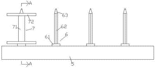
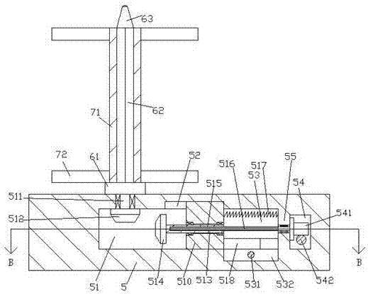
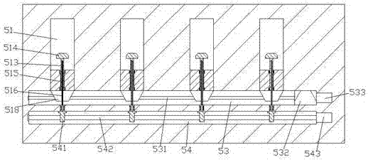
[0021] Such as Figure 1-Figure 6 As shown, a textile winding mechanism capable of self-selective control and driving of the present invention includes a base 5 and winding mechanisms 6 equidistantly distributed on the top end surface of the base 5, and the winding mechanism 6 below each winding mechanism 6 The base 5 is provided with a driving cavity 51 extending to the front side, and the rear side of the driving cavity 51 is communicated with a first cavity 53 extending left and right, and the inside of the base 5 on the front side of the first cavity 53 is A second cavity 54 is provided, a partition 55 is provided between the first cavity 53 and the second cavity 54, and a guide slide is provided on the inner top wall of the front side of each first cavity 53 Slots 52, each sliding block 52 is provided with a sliding block 510 extending downwards, the bottom extension section of the sliding block 510 extends into the driving cavity 51 and is connected to the bottom wall of...


PUM


Abstract

The invention discloses a spinning winding mechanism capable of selecting control drive by itself. The spinning winding mechanism comprises a base and winding mechanisms distributed on the end face of the top of the base at equal intervals. The part, below each winding mechanism, of the base is internally provided with a drive cavity extending towards the front side, wherein the rear side of the drive cavity communicates with a first cavity extending left and right, a second cavity is formed in the part, on the front side of the first cavity, in the base, and a partition plate is arranged between the first cavity and the second cavity. A guiding and sliding groove is formed in the inner top wall of the front side of each first cavity. Each guiding and sliding groove is internally provided with a sliding block downwards extending. The bottom extending sections of the sliding blocks stretch into the drive cavities and are connected with the inner bottom walls of the drive cavities in a sliding fit manner. Each sliding block is internally connected with a first rotation shaft in a rotation fit manner, wherein the first rotation shaft extends towards the rear side. The spinning winding mechanism is simple in structure, installation of multiple winding barrels can be achieved, the winding barrels do not need to be replaced after being subjected to winding, time and labor are saved, and efficiency is improved. In addition, a drive device does not need to be additionally arranged, the manufacturing cost is reduced, and meanwhile the purchasing cost of enterprises is reduced.

Description

technical field [0001] The invention relates to the technical field of textile processing machinery, in particular to a textile winding mechanism capable of self-selective control and driving. Background technique [0002] In the textile industry, a neat and uncluttered coil is the prerequisite for weaving good products. Therefore, since ancient times, people have arranged the threads before weaving, and wound them into a neat ball for storage and transportation. Or the textile work in the next process, it is one of the very important textile machinery and equipment in modern textile enterprises. In the existing winding device, there is often only a single winding, and the work efficiency is low. After one winding, the winding barrel needs to be replaced, and then the winding is continued, which is a waste of man-hours and low in efficiency. In addition, if more The winding device requires an additional driving device, which increases the cost and is very inconvenient to us...

Claims


Application Information

Patent Timeline
Patent Type & Authority Applications(China)
IPC IPC(8): B65H54/20B65H54/74
CPCB65H54/20B65H54/74B65H2403/43B65H2403/46B65H2403/52B65H2403/55
Inventor 何海燕
Owner 桐乡市建泰纺织有限公司
Learn More