
Aluminum core surface spraying device

A surface spraying, aluminum core technology, applied in the field of aluminum core, can solve the problems of waste, large waste, difficult to process aluminum core and the aluminum core is not firmly installed, and achieve the effect of firm and stable installation

Active Publication Date: 2017-11-03
ANHUI SHENGMEI METAL TECH CO LTD
View PDF7 Cites 1 Cited by
  • Summary
  • Abstract
  • Description
  • Claims
  • Application Information

AI Technical Summary

Problems solved by technology

[0002] For industrial aluminum core products, it is necessary to spray adhesive on a section of the position, and then perform rubber bonding treatment. Since only one section needs to be sprayed with glue, currently the sheath is sprayed together with the aluminum core, and no spraying is required to cover it. After the spraying is completed, just remove the sheath; the defect of the existing technology: a lot of spraying on the plastic sheath, the adhesive is expensive and wasteful
The other side of the body is provided with a guide rail, the guide rail is provided with a tailstock, the tailstock is engaged with the rack and pinion of the guide rail, the tail of the tailstock is provided with a handwheel, and the side of the tailstock is provided with another Handwheel, the front end of the tailstock is provided with a top shaft, although the problem of waste of resources is solved, but there is still the problem that it is not easy to process different types of aluminum cores and the installation of the aluminum cores is not firm

Method used

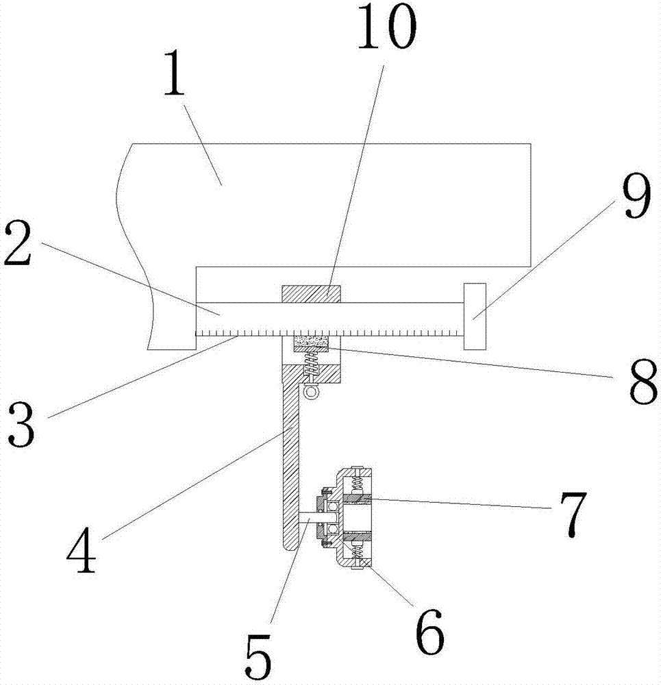

Image

  • Aluminum core surface spraying device
  • Aluminum core surface spraying device
  • Aluminum core surface spraying device

Examples


Embodiment Construction

[0018] The following will clearly and completely describe the technical solutions in the embodiments of the present invention with reference to the accompanying drawings in the embodiments of the present invention. Obviously, the described embodiments are only some, not all, embodiments of the present invention. Based on the embodiments of the present invention, all other embodiments obtained by persons of ordinary skill in the art without making creative efforts belong to the protection scope of the present invention.

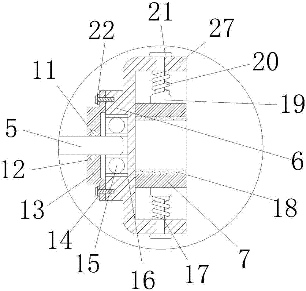
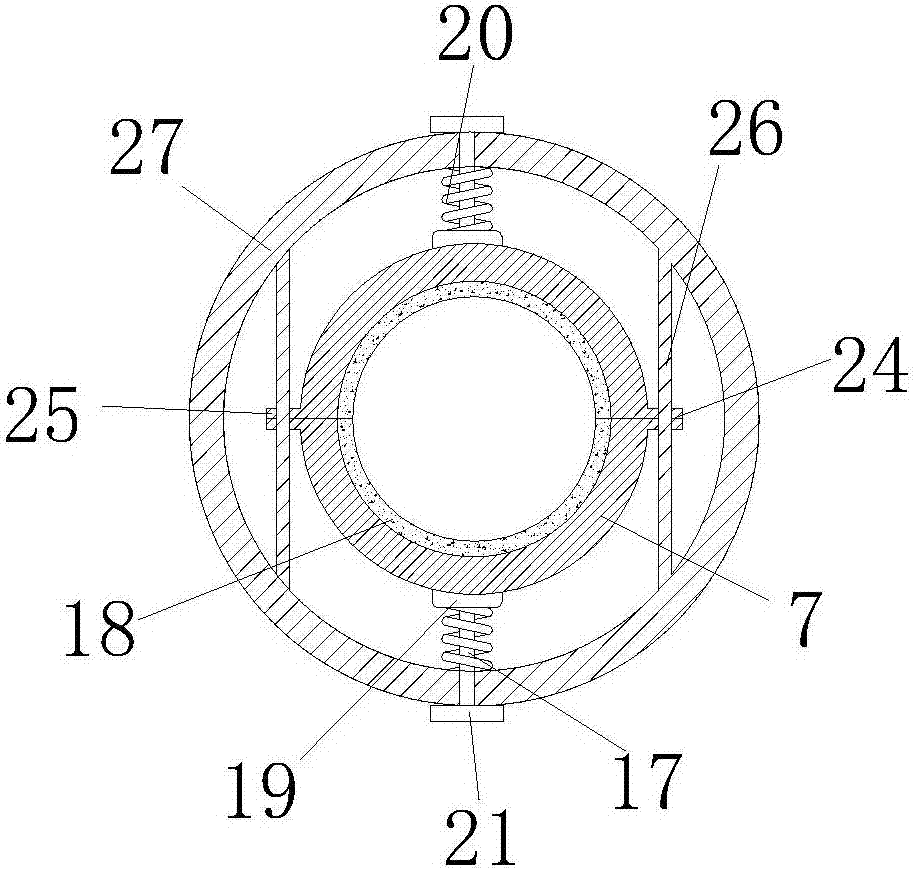
[0019] see Figure 1-4 , the present invention provides a technical solution: an aluminum core surface spraying device, including a plastic box 1, a slide bar 2 is provided at the lower left corner of the plastic box 1, and a scale 3 is provided on the lower surface of the slide bar 2, and the scale is used for convenient observation , the right end of the slide bar 2 is provided with a top block 9, the outer surface of the slide bar 2 is provided with a slide...


PUM


Abstract

The invention discloses an aluminum core surface spraying device which comprises a glue box; a sliding bar is arranged at the lower left corner of the glue box; a sliding block is arranged on the outer surface of the sliding bar; struts are arranged at the lower surfaces of first clamping blocks; the struts penetrate through a cylinder and are connected with cushion blocks; first springs are arranged on the upper surfaces of the cushion blocks; the cushion blocks are connected with the cylinder through the first springs; fasteners are arranged at the lower surfaces of the cushion blocks; gaskets are arranged at the left end and the right end of each fastener; through holes are formed in the surfaces of the gaskets; metal connecting rods are arranged in the through holes; and the upper end and the lower end of each metal connecting rod are connected with the inner wall of the cylinder. According to the aluminum core surface spraying device, the fasteners are pushed towards the upper end and the lower end and then the fasteners push the cushion blocks to move, the cushion blocks are pushed to move to the center by the first springs, the fasteners are pushed to move by the cushion blocks, and an aluminum core is clamped by interaction force between the fasteners, so that a filter element is mounted more securely and stably.

Description

technical field [0001] The invention relates to the technical field of aluminum cores, in particular to an aluminum core surface spraying device. Background technique [0002] For industrial aluminum core products, it is necessary to spray adhesive on a section of the position, and then perform rubber bonding treatment. Since only one section needs to be sprayed with glue, currently the sheath is sprayed together with the aluminum core, and no spraying is required to cover it. After the spraying is completed, just remove the sheath; the defect of the existing technology: many sprays are sprayed on the plastic sheath, and the adhesive is expensive and wasteful. The sheath needs to be removed after spraying the adhesive before it can continue to be used. Cleaning the sheath is very troublesome and takes a long time. The chuck is connected on the motor main shaft, and the motor is fixedly connected on the machine body. The other side of the body is provided with a guide rail,...

Claims


Application Information

Patent Timeline
IPC IPC(8): B05C13/02B05B15/04B05B13/02
CPCB05B12/20B05B13/0285B05C13/02
Inventor 凌永娥
Owner ANHUI SHENGMEI METAL TECH CO LTD
Learn More