Cover assembly and mobile terminal including same
A mobile terminal and cover plate technology, applied in electrical components, digital data processing parts, instruments, etc., can solve problems such as halo when taking pictures with the front camera, and achieve the effect of weakening the halo problem
- Summary
- Abstract
- Description
- Claims
- Application Information
AI Technical Summary
Problems solved by technology
Method used
Image
Examples
Embodiment 1
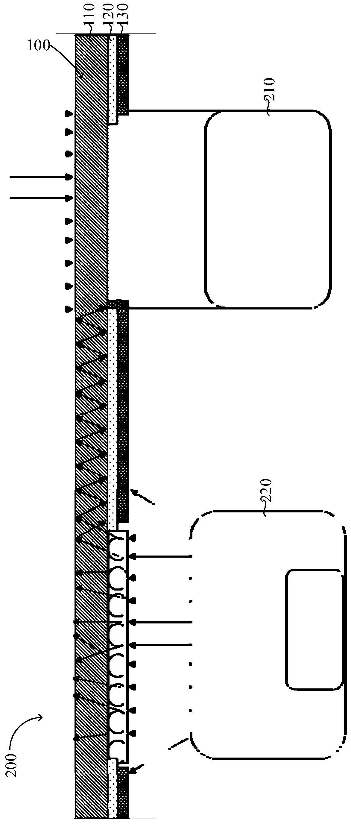
[0046] like figure 1 As shown, a cover plate assembly 100 includes a cover plate 110 , a first ink layer 120 , and a second ink layer 130 stacked in sequence. The first ink layer 120 is a reflective ink layer, and the second ink layer 130 is a light-absorbing ink layer. The first ink layer 120 is provided with a first camera aperture 121 , and the second ink layer 130 is provided with a second camera aperture 131 . The first imaging opening 121 and the second imaging opening 131 are used for allowing light to enter and exit the imaging component. The second ink layer 130 covers part of the first imaging aperture 121 . In this embodiment, the first ink layer 120 is a white ink layer, and the white ink reflects light; the second ink layer 130 is a black ink layer, and the black ink absorbs light. See figure 1 , the second ink layer 130 on one side of the second imaging opening 131 covers part of the first imaging opening 121 .
[0047] like figure 2 As shown, a mobile ter...
Embodiment 2
[0049] like image 3 As shown, a cover plate assembly 100 includes a cover plate 110 , a first ink layer 120 , and a second ink layer 130 stacked in sequence. The first ink layer 120 is a reflective ink layer, and the second ink layer 130 is a light-absorbing ink layer. The first ink layer 120 is provided with a first camera aperture 121 , and the second ink layer 130 is provided with a second camera aperture 131 . The first imaging opening 121 and the second imaging opening 131 are used for light to enter and exit the imaging component, and the second ink layer 130 covers part of the first imaging opening 121 . In this embodiment, the first ink layer 120 is a white ink layer, and the white ink reflects light; the second ink layer 130 is a black ink layer, and the black ink absorbs light. In an alternative embodiment, the first ink layer 120 may be other light colored ink layers.
[0050] The first ink layer 120 is further provided with a first light-emitting opening 122 , ...
Embodiment 3
[0058] like Figure 5 As shown, the third embodiment is substantially the same as the second embodiment, except that no blocking medium is provided at the first light emitting opening 122 and the second light emitting opening 132 . The first imaging opening 121 completely covers the second imaging opening 131 , and the distance between the boundary of the first imaging opening 121 and the boundary of the second imaging opening 131 is not less than 0.2 mm. The light emitted from the light-emitting component 220 will not be diffused through the blocking medium 140, therefore, the light entering the imaging component 210 from the first imaging opening 121 and the second imaging opening 131 will be reduced compared to the second embodiment. At this time, only 0.2 mm of the ink that crosses the boundary of the second ink layer 130 is needed to basically completely solve the problem of halation.
PUM
 Abstract
Description
Claims
Application Information
 - R&D
- Intellectual Property
- Life Sciences
- Materials
- Tech Scout
- Unparalleled Data Quality
- Higher Quality Content
- 60% Fewer Hallucinations
Browse by: Latest US Patents, China's latest patents, Technical Efficacy Thesaurus, Application Domain, Technology Topic, Popular Technical Reports.
© 2025 PatSnap. All rights reserved.Legal|Privacy policy|Modern Slavery Act Transparency Statement|Sitemap|About US| Contact US: help@patsnap.com


