Automatic full testing equipment for precision parts
A technology for testing equipment and precision parts, which is applied in the field of automatic full testing equipment for precision parts, can solve problems such as easy omission or false detection, low chamfering efficiency, and high difficulty in manual detection, so as to improve work efficiency, avoid detection blind spots, The effect of a clear field of view
- Summary
- Abstract
- Description
- Claims
- Application Information
AI Technical Summary
Problems solved by technology
Method used
Image

Examples
Embodiment 1
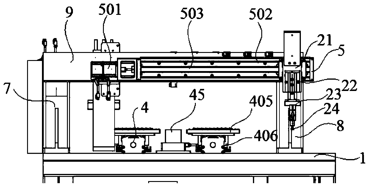
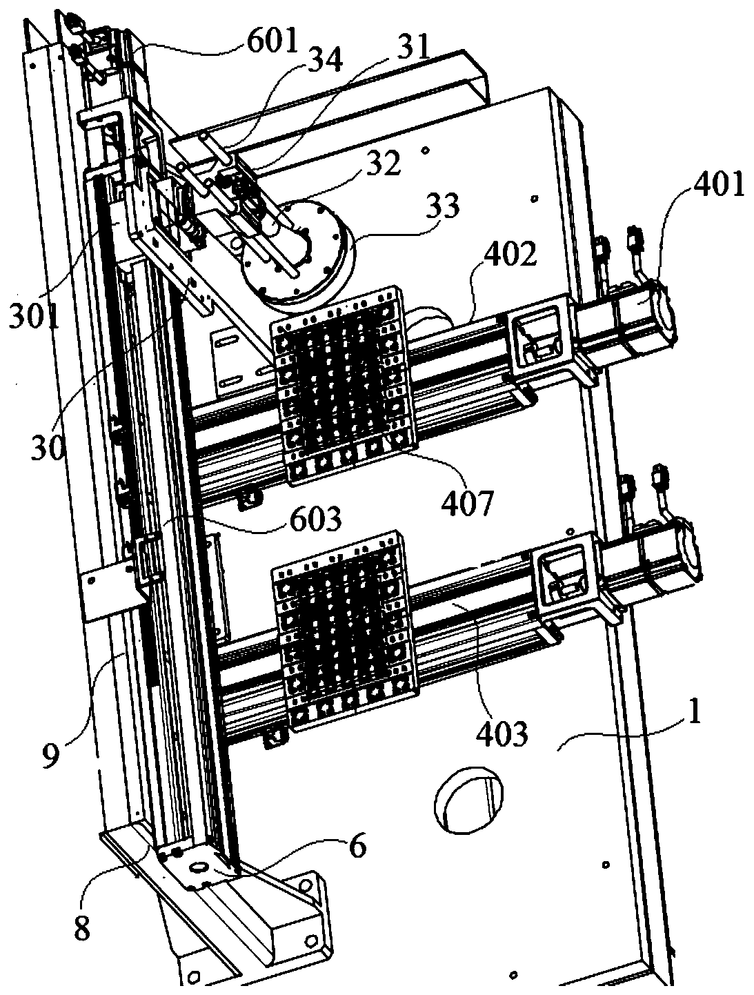
[0025] Embodiment 1: An automatic full detection equipment for precision parts, including a base 1, a support frame 2 installed on the base 1, a material transport mechanism 4, a front-end transmission device 5 and a rear-end transmission device 6, the support frame 2 is from the left Upright post 7, right upright post 8 and crossbeam 9 are formed, and this left upright post 7, right upright post 8 are respectively fixed on both sides of base 1 upper surface, and described crossbeam 9 bridges over the top of left upright post 7, right upright post 8, and described transmission device 3 respectively installed on the upper surface of the base 1 and the front and rear sides of the crossbeam 9 of the support frame 2;
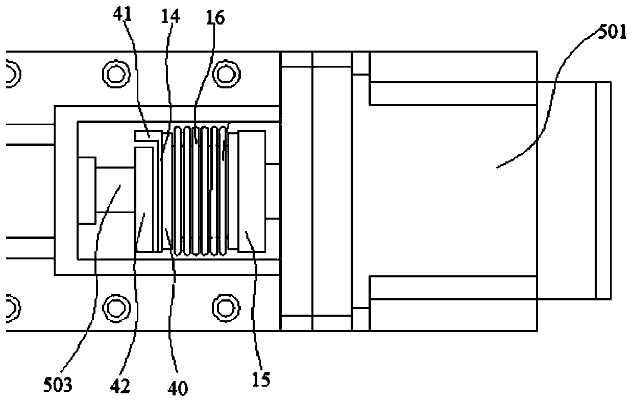
[0026] Described conveying mechanism 4 further comprises motor 401, screw mandrel 403, nut 404 and carrier plate 405, and described motor 401 is installed on base 1 and is opposite to feed inlet one end, and described screw mandrel 403 is installed on the base 1 and ...
Embodiment 2
[0033] Embodiment 2: An automated full detection equipment for precision parts, including a base 1, a support frame 2 installed on the base 1, a material transport mechanism 4, a front-end transmission device 5 and a rear-end transmission device 6, the support frame 2 is from the left Upright post 7, right upright post 8 and crossbeam 9 are formed, and this left upright post 7, right upright post 8 are respectively fixed on both sides of base 1 upper surface, and described crossbeam 9 bridges over the top of left upright post 7, right upright post 8, and described transmission device 3 respectively installed on the upper surface of the base 1 and the front and rear sides of the beam 9 of the support frame 2;
[0034] Described conveying mechanism 4 further comprises motor 401, screw mandrel 403, nut 404 and carrier plate 405, and described motor 401 is installed on base 1 and is opposite to feed inlet one end, and described screw mandrel 403 is installed on the base 1 and is co...
PUM
 Abstract
Description
Claims
Application Information
 - R&D
- Intellectual Property
- Life Sciences
- Materials
- Tech Scout
- Unparalleled Data Quality
- Higher Quality Content
- 60% Fewer Hallucinations
Browse by: Latest US Patents, China's latest patents, Technical Efficacy Thesaurus, Application Domain, Technology Topic, Popular Technical Reports.
© 2025 PatSnap. All rights reserved.Legal|Privacy policy|Modern Slavery Act Transparency Statement|Sitemap|About US| Contact US: help@patsnap.com