
Digital quantity wireless valve controller

A valve controller and controller technology, applied in the direction of valve details, valve devices, valve operation/release devices, etc., can solve problems that affect the stability of PLC's control of valves, line aging, etc.

Pending Publication Date: 2017-10-24
安徽能测能控科技有限公司
View PDF6 Cites 2 Cited by
  • Summary
  • Abstract
  • Description
  • Claims
  • Application Information

AI Technical Summary

Problems solved by technology

[0004] The purpose of the present invention is to provide a digital wireless valve controller to solve the problem that the valves proposed in the above background technology are remotely monitored by the PLC through the bus to the valves in different positions, which leads to the need to lay a large number of cables during construction. The laid cables are seriously aging due to long-term outdoors, which affects the stability of the PLC's control of the valve.

Method used


Image

  • Digital quantity wireless valve controller
  • Digital quantity wireless valve controller
  • Digital quantity wireless valve controller

Examples


Embodiment

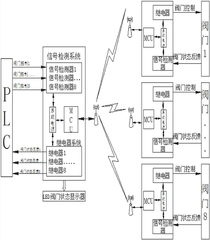
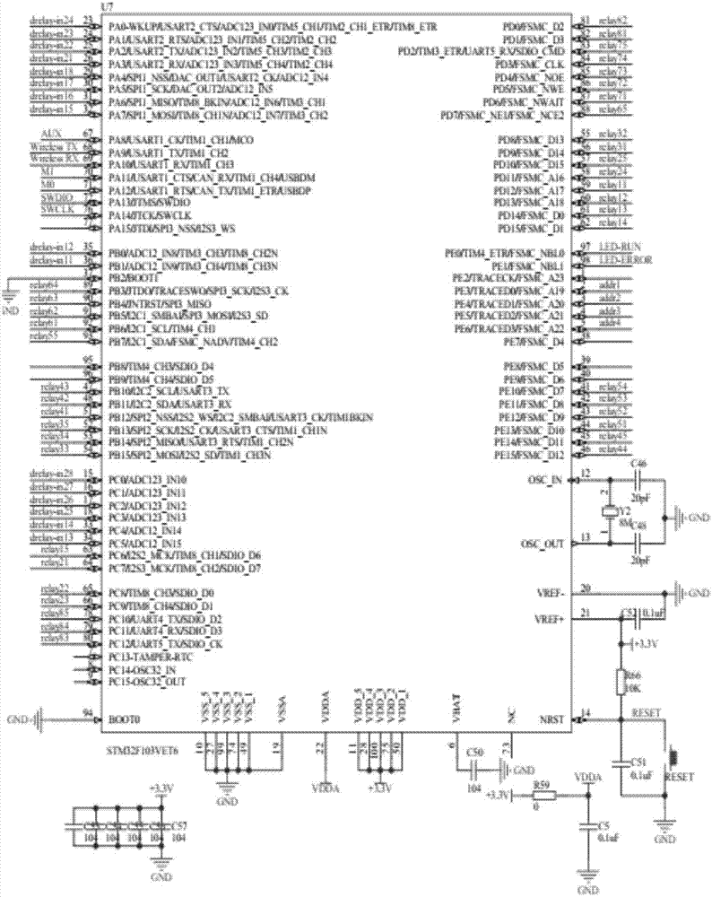
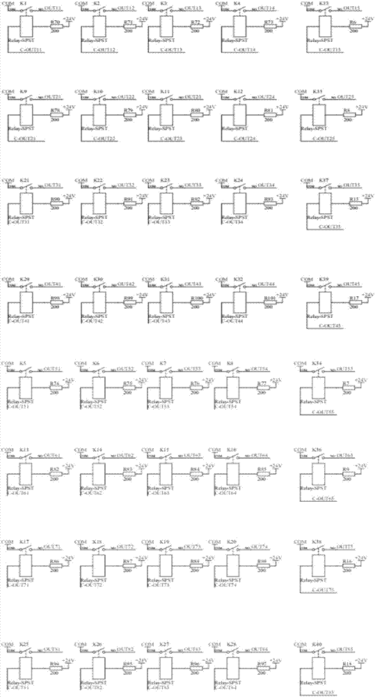
[0031] Such as Figure 1 to Figure 4 As shown, the model of the MCU in the upper controller of the wireless valve is STM32F103VET6, and the relay in the upper controller of the wireless valve is driven by the relay driver ULN2803A. To drive a relay in a digital wireless valve controller, the ULN2803A has 18 pins, of which ULN2803A is divided into input terminals and output terminals, and the number of both ports is the same as 9, of which the input terminal of ULN2803A is the most The lower port is grounded, and the lowermost port of the output end is connected to the 24V power supply. The input end of U10 is connected to the port 59 to port 66 of the MCU in the upper controller of the wireless valve in sequence from top to bottom, and the output end is connected to the relay in turn from top to bottom. From K1 to K4, K33, K5 to K7, the input terminal of U11 is connected to port 58 to port 51 of the MCU in the upper controller of the wireless valve from top to bottom in sequen...


PUM


Abstract

The invention discloses a digital quantity wireless valve controller which comprises a wireless valve upper end controller and at least one wireless valve lower end controller. The wireless valve upper end controller is composed of a system power supply, an MCU, a signal detection system and a relay system, wherein the MCU, the signal detection system and the relay system are in electric bidirectional connection with the system power supply. Each wireless valve lower end controller is composed of a system power supply, an MCU, a relay and a signal detector, wherein the MCU, the relay and the signal detector are in electric bidirectional connection with the system power supply. A PLC is connected with the wireless valve upper end controller. A valve is connected with the wireless valve lower end controller. The wireless valve upper end controller is in communication connection with the wireless valve lower end controller through a wireless signal receiving and transmitting unit. According to the digital quantity wireless valve controller, through wireless monitoring and controlling modes, remote control and state monitoring on a series of valves are achieved, thus, no line needs to be laid between the valve controllers, cost input is reduced, and relatively stable operation of the valve is guaranteed.

Description

technical field [0001] The invention relates to the field of valve remote control, in particular to an analog wireless valve controller. Background technique [0002] Wireless control is a major event in the development of control technology at present. In industrial processing and production, wireless control has become indispensable in industrial processing with small input cost and stable control performance. [0003] In the prior art, many valves in the current valve control application are remotely monitored by the PLC through the bus to the valves in different positions. When establishing such a control system, it is necessary to lay a large number of cables, which not only increases the amount of construction Moreover, the cost is increased. In the later maintenance, the cables that have been laid outdoors for a long time cause serious line aging, which makes maintenance more difficult and affects the stability of the equipment. Contents of the invention [0004] T...

Claims


Application Information

Patent Timeline
IPC IPC(8): F16K31/02F16K37/00
CPCF16K31/02F16K37/0058F16K37/0075
Inventor 盛琦
Owner 安徽能测能控科技有限公司
Learn More