
Self-adaption torque balance drill bit

A torque balance and self-adaptive technology, applied in the direction of drill bits, drilling tools, drilling equipment, etc., can solve the problems of drill bit or bottom hole assembly fatigue damage, improve the drilling efficiency of the drill bit, and cannot actively control the penetration depth, etc. , to achieve the effect of good direction control stability, reduction of non-production time, simple principle and structure

Active Publication Date: 2017-10-24
CHINA UNIV OF PETROLEUM (EAST CHINA)
View PDF7 Cites 3 Cited by
  • Summary
  • Abstract
  • Description
  • Claims
  • Application Information

AI Technical Summary

Problems solved by technology

Since the main drill bit in the field of oil exploration—PDC bit (English: Polycrystalline Diamond Compact bit) has a strong selectivity to formations, when drilling hard formations or multi-interlayer formations, the stick-slip phenomenon and the resulting impact damage will cause Lower ROP, less footage per drill bit and greatly extended well construction period
Although the above-mentioned existing drill bit can be equipped with a penetration control unit, since the penetration depth cannot be actively controlled when drilling into complex formations, there is still the potential for stick-slip phenomenon, resulting in strong torque fluctuations of the drill bit during drilling , causing fatigue damage to the drill bit or bottom hole assembly, and failing to optimize the drilling efficiency of such bits

Method used


Image

  • Self-adaption torque balance drill bit
  • Self-adaption torque balance drill bit
  • Self-adaption torque balance drill bit

Examples


Embodiment Construction

[0031] Hereinafter, the present invention will be specifically described through exemplary embodiments. It should be understood, however, that elements, structures and features of one embodiment may be beneficially combined in other embodiments without further recitation.

[0032]In the description of the present invention, it should be noted that the length direction of the self-adaptive torque balance drill bit is the vertical direction after installation; the terms "inner", "outer", "upper", "middle", "lower", etc. The orientation or positional relationship is based on the positional relationship shown in the accompanying drawings, which is only for the convenience of describing the present invention and simplifying the description, rather than indicating or implying that the referred device or element must have a specific orientation, be constructed and operated in a specific orientation, Therefore, it should not be construed as a limitation of the present invention. Furt...


PUM


Abstract

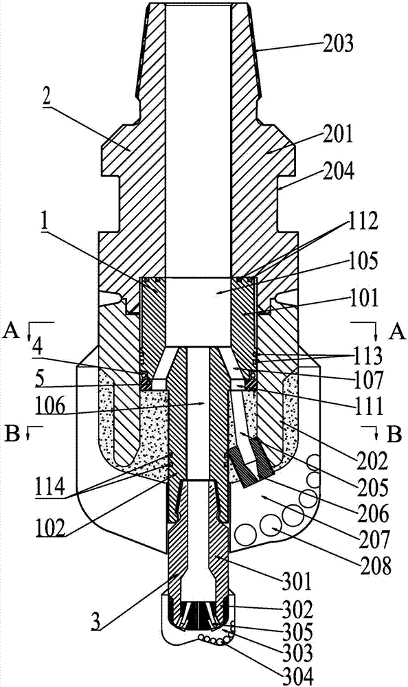
The invention relates to a self-adaption torque balance drill bit comprising a hole reaming drill bit body and a hole piloting drill bit body. The hole reaming drill bit body comprises a hole reaming drill bit connector and a hole reaming drill bit crown. The hole piloting drill bit body is mounted in the hole reaming drill bit crown and protrudes out of the hole reaming drill bit crown, and a torque transmission device is mounted in an inner cavity formed by connecting the hole reaming drill bit connector and the hole reaming drill bit crown. The torque transmission device comprises a rotating piece and a transmission piece fixedly connected with the rotating piece, the transmission piece is connected with the hole piloting drill bit body, and at least one retainer is arranged on the rotating piece. The torque transmission device further comprises limiting pieces matched with the retainers, and the limiting pieces are arranged on the hole reaming drill bit crown. Elastic pieces matched with the retainers for using and used for transmitting partial hole piloting drill bit rock breaking torque and buffering torque fluctuation are arranged between the retainers and the hole reaming drill bit crown. According to the self-adaption torque balance drill bit, drill bit torque fluctuation in the drilling process can be controlled in a self-adaption mode, and torsion impact vibration generated by the stick-slip phenomenon in the drilling process is slowed down and even avoided.

Description

technical field [0001] The invention belongs to the technical field of petroleum engineering, relates to drilling tools, in particular to an adaptive torque balance drill bit. Background technique [0002] Drilling field practice shows that by changing the structure of the bottom hole during the drilling process, the bottom hole formation stress can be released in advance and the rock breaking efficiency of the drill bit can be effectively improved. Based on the above principles, foreign NOV companies have developed concentric dual-stage Speed ​​DrillBits, and domestic Shengli Drilling Institute Peng Ye has developed dual-stage PDC drill bits. [0003] The Chinese invention patent application with publication number CN105443041A discloses a differential pressure drill bit, and specifically discloses the following features: the differential pressure drill bit includes an adapter, a short connection for liquid transmission and force transmission, a reaming bit, a force accumul...

Claims


Application Information

Patent Timeline
IPC IPC(8): E21B10/28E21B12/00
CPCE21B10/28E21B12/00
Inventor 管志川呼怀刚刘永旺
Owner CHINA UNIV OF PETROLEUM (EAST CHINA)
Learn More