
Device for automatically conveying pump head

An automatic conveying and pump head technology, which is applied in the direction of conveyors, conveyor objects, transportation and packaging, etc., can solve the problems of unfavorable packaging production efficiency, unfavorable packaging production quality, and leakage of bottle mouth 121, so as to reduce manpower input, The effect of reducing the labor intensity of workers and facilitating maintenance

Inactive Publication Date: 2017-10-24
QUANZHOU HUASHUO IND
View PDF11 Cites 0 Cited by
  • Summary
  • Abstract
  • Description
  • Claims
  • Application Information

AI Technical Summary

Problems solved by technology

This kind of production method in which workers manually place and tighten the pump head 11 has a slow production speed, which is not conducive to further improving the packaging production efficiency; in addition, in the packaging production process, it is often prone to the phenomenon that the screwing is not in place, resulting in 121 bottle openings. There is a problem of liquid leakage, which is not conducive to further improving the quality of packaging production; in addition, on each packaging production line, it is often necessary to arrange more workers to manually place and tighten the pump head 11 at the same time, in order to meet the production speed requirements of the production line , which is not conducive to labor saving, workers need to continuously tighten the pump head 11, and the labor intensity of workers is also relatively high

Method used


Image

  • Device for automatically conveying pump head
  • Device for automatically conveying pump head
  • Device for automatically conveying pump head

Examples


Embodiment Construction

[0018] Preferred embodiments of the present invention will be described in detail below in conjunction with the accompanying drawings.

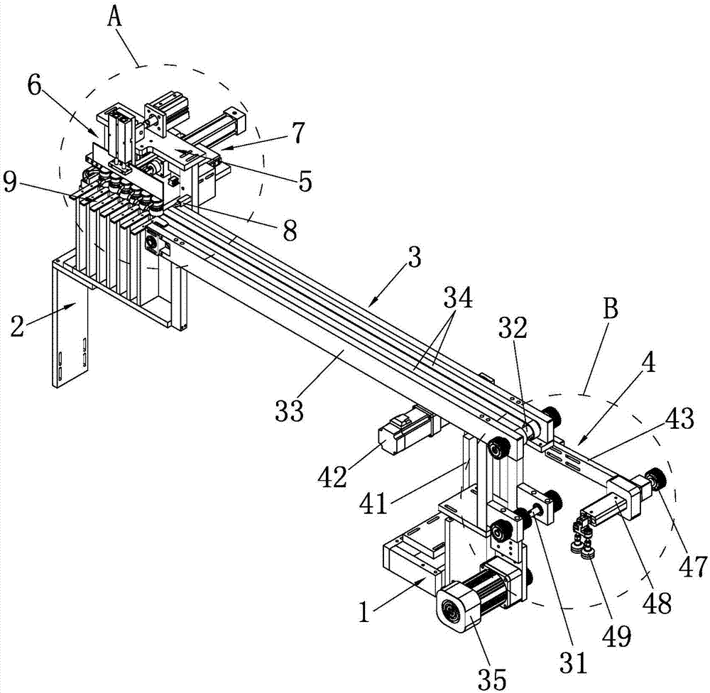
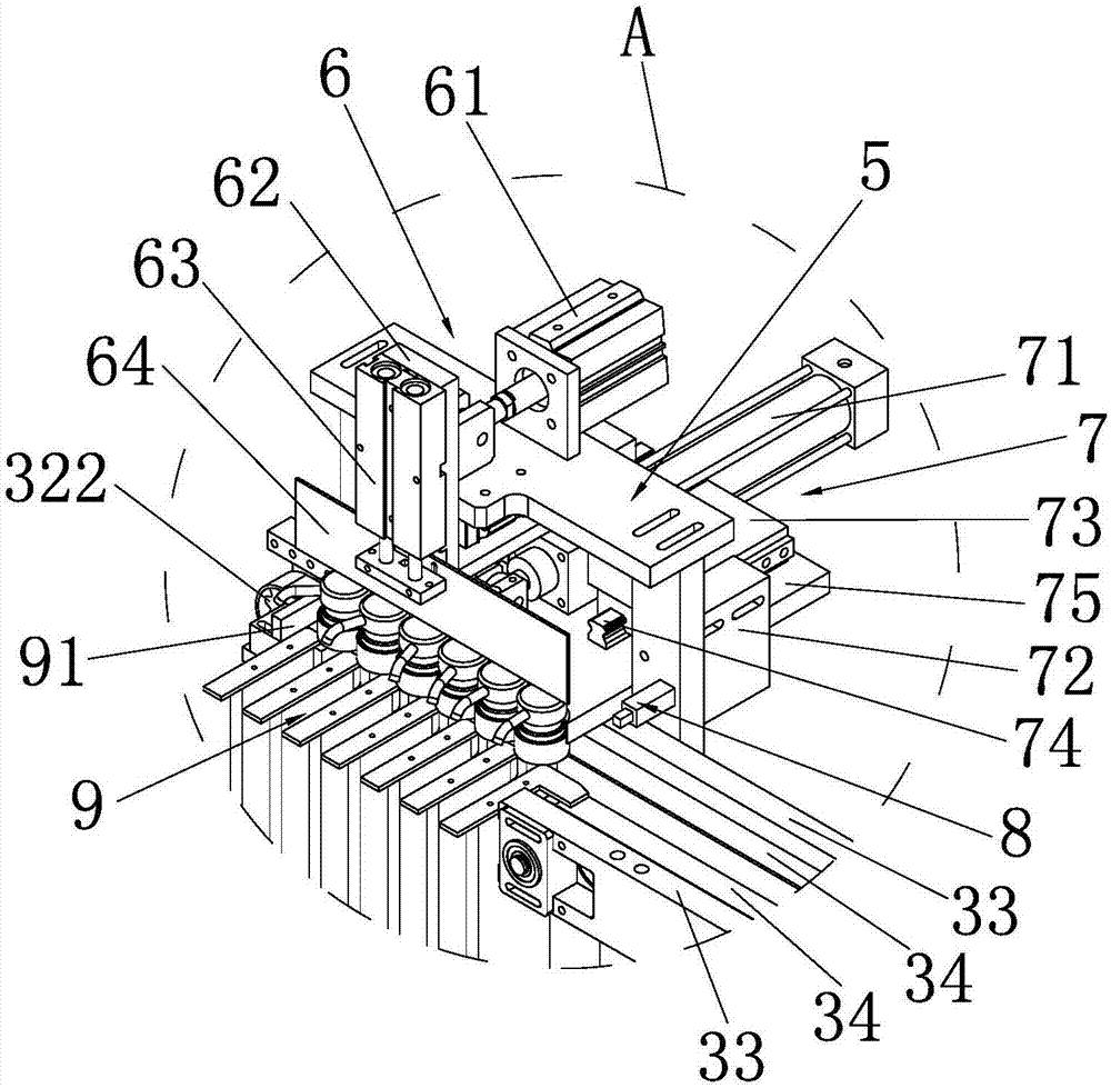
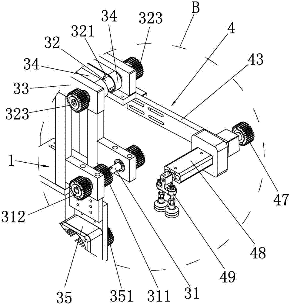
[0019] Such as Figure 1 to Figure 8 As shown, a device for automatically transporting pump heads includes a first mounting bracket 1, a second mounting bracket 2, a delivery track 3, a retrieving mechanism 4, a third mounting bracket 5, a stopper mechanism 6, and a feeding mechanism 7 , a sensor 8 and a feeding trough 9; the bottom of the feeding end of the conveying track 3 is provided with a first mounting bracket 1, and the first mounting bracket 1 is provided with a reciprocating and rotating retrieving mechanism 4; the outlet of the conveying track 3 The bottom of the feed end is provided with a second mounting bracket 2, and the second mounting bracket 2 is provided with a feed tank 9 for conveying the pump head 11, and the front end top of the feed tank 9 is connected with the conveying track 3, and the rear end top of the feed tank 9...


PUM


Abstract

The invention provides a device for automatically conveying a pump head. The device comprises a first mounting support, a second mounting support, a conveying rail, a taking mechanism, a feeding groove, a third mounting support, a sensor, a stop mechanism and a feeding mechanism. The first mounting support is arranged at the bottom of the feeding end of the conveying rail, the taking mechanism is arranged on the first mounting support, the bottom of the discharging end of the conveying rail is provided with the second mounting support, the feeding groove is formed in the second mounting support, the top of the rear end of the feeding groove is provided with a check block, the third mounting support is arranged on the side wall of the discharging end of the conveying rail, the sensor, the stop mechanism and the feeding mechanism are arranged on the third mounting support, the taking mechanism conveys the pump head to the feeding end of the conveying rail, the conveying rail conveys the pump head to the discharging end from the feeding end, the pump head is stopped and position through the stop mechanism, and the feeding mechanism is used for pushing the pump head into the feeding groove. According to the device, the pump head can be automatically conveyed, and the package production efficiency of the pump head and a bottle body can be greatly improved.

Description

technical field [0001] The invention relates to an automatic delivery device, in particular to a device for automatic delivery of pump heads. Background technique [0002] Such as Figure 8 Shown is an existing packaging bottle for packaging liquids. The packaging bottle includes a bottle body 12 and a pump head 11. The top of the bottle body 12 is provided with a bottle mouth 121. The bottom end of the pump head 11 is a liquid inlet. The top of the head 11 is the liquid outlet, and the bottom of the pump head 11 extends into the bottle mouth 121 , and then the pump head 11 is screwed and installed on the bottle body 12 . In the existing production technology, when using the packaging bottle for packaging production, the worker first fills the bottle body 12 with liquid, and then manually puts the pump head 11 from the bottle mouth 121 into the bottle body 12, and the worker The pump head 11 is manually tightened, and the pump head 11 is tightened and fixedly installed on t...

Claims


Application Information

Patent Timeline
Patent Type & Authority Applications(China)
IPC IPC(8): B65G15/22B65G47/90
CPCB65G15/22B65G47/904
Inventor 朱世钦唐宇蔡金根辜少芳
Owner QUANZHOU HUASHUO IND
Learn More