Draw-bar suitcase being capable of auto-moving

A technology of automatic movement and luggage, applied in the field of luggage, can solve the problems of complex structure, high cost and high failure rate, and achieve the effect of simple structure, cultivating sentiment, and avoiding hand clamping.

Inactive Publication Date: 2017-10-24
合肥赛格汽车服务有限公司
View PDF2 Cites 0 Cited by
  • Summary
  • Abstract
  • Description
  • Claims
  • Application Information

AI Technical Summary

Problems solved by technology

This system realizes the function of the luggage automatically following the owner when people travel with luggage without human intervention. The distance between the luggage and the owner is monitored in real time, which solves people's worries about luggage being stolen, and can easily realize luggage weight and luggage vibration data. monitoring, truly realize the expansion of various functions of bags, and truly realize the intelligence of bags, but the cost is high, the structure is complex, and the failure rate is high

Method used


Image

  • Draw-bar suitcase being capable of auto-moving
  • Draw-bar suitcase being capable of auto-moving
  • Draw-bar suitcase being capable of auto-moving

Examples


Embodiment 1

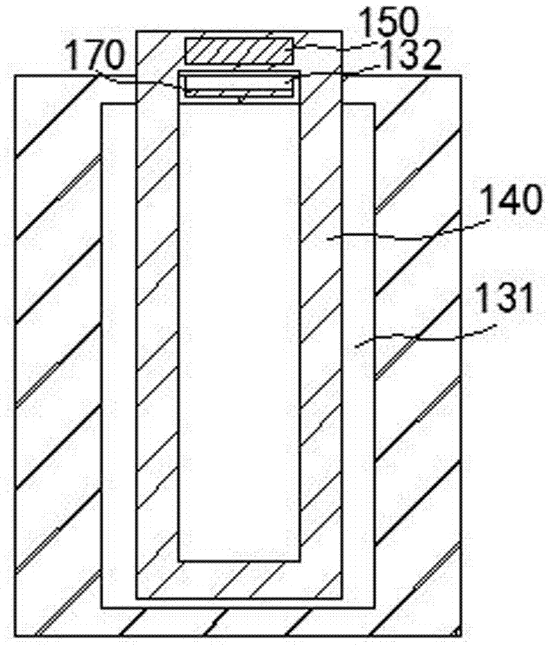
[0034] Such as Figure 1-4 As shown, it is a hand-held case that can move automatically in this embodiment, including a case body 110. The bottom end of the case body 110 is provided with a left roller 121 and a right roller 122. The right roller 122 is driven to rotate by a motor 210, and the case body 110 A mounting plate 130 is provided on the right side of 100, and a closed mounting cavity 131 is provided in the mounting plate 130, a pull rod 140 is inserted in the mounting cavity 131 and the top end passes through the mounting plate 130;

[0035] The luggage body 110 is provided with a microprocessor for calculation processing, a battery for providing power, a wireless communication module for wireless transmission and a speed sensor for detecting the speed of the right roller 122, the wireless communication module, the battery, the speed sensor and The motors 210 are all connected to the microprocessor; the top of the pull rod 140 is provided with a remote control switch...

Embodiment 2

[0051] Such as Figure 2-5 As shown, it is a hand-held case that can move automatically in this embodiment, including a case body 110. The bottom end of the case body 110 is provided with a left roller 121 and a right roller 122. The right roller 122 is driven to rotate by a motor 210. The case body 110 A mounting plate 130 is provided on the right side of 100, and a closed mounting cavity 131 is provided in the mounting plate 130, a pull rod 140 is inserted in the mounting cavity 131 and the top end passes through the mounting plate 130;

[0052] The luggage body 110 is provided with a microprocessor for calculation processing, a battery for providing power, a wireless communication module for wireless transmission and a speed sensor for detecting the speed of the right roller 122, the wireless communication module, the battery, the speed sensor and The motors 210 are all connected to the microprocessor; the top of the pull rod 140 is provided with a remote control switch 150...


PUM


Abstract

The invention discloses a draw-bar suitcase being capable of auto-moving and relates to the technical field of suitcases. The draw-bar suitcase includes a suitcase body. A left rolling wheel and a right rolling wheel are disposed on the bottom of the suitcase body. The right rolling wheel is driven to rotate by a motor. A mounting board is arranged on the right side of the suitcase body. A sealed mounting cavity is disposed in the mounting board. A drawing bar is inserted in the mounting cavity, the top end of the drawing bar stretched out from the mounting board. In interior of the suitcase body, a microprocessor for computing, a storage battery for power supply, a wireless communication module for wireless transmission, and a rotary speed sensor for detecting the rotary speed of the right rolling wheel are disposed. The wireless communication module, the storage battery, the rotary speed sensor and the motor are all connected to the microprocessor. A remote control switch is arranged on the top of the drawing rod and is wirelessly connected to the wireless communication module. The draw-bar suitcase can effectively move automatically, so that the draw-bar suitcase saves effort when people pulling it, and also can prevent hands from being snapped when the drawing bar is retracted.

Description

technical field [0001] The invention belongs to the technical field of luggage, and in particular relates to a hand-held luggage that can move automatically. Background technique [0002] A trolley case is a kind of luggage, which refers to a suitcase with a trolley and rollers. It is widely used because of its convenient use, carrying clothes, etc. for travel and going out. [0003] At the same time, the trolley case is also equipped with a trolley, which can be divided into single-tube trolley and double-tube trolley. [0004] The trolley case can be carried or dragged. The wheels of the trolley case we usually use are basically located at the bottom of the case, and modern people have designed a new form of the trolley case. The case is designed in the shape of a cylinder, and the wheels are The entire outsourcing is on the outside of the box. This roller design makes this trolley box better adapt to different terrains. For example, you can easily go up and down the sta...

Claims


Application Information

Patent Timeline
Patent Type & Authority Applications(China)
IPC IPC(8): A45C5/14A45C13/00A45C13/26A45C13/28A45C15/00G05B19/042
CPCA45C5/14A45C13/001A45C13/262A45C13/28A45C15/00G05B19/0423
Inventor 不公告发明人
Owner 合肥赛格汽车服务有限公司
Why Eureka
Try Eureka