LED light emitting driving circuit
A light-emitting drive and circuit technology, applied in the semiconductor field, can solve problems such as large current deviation and uneven brightness of LEDs in LED matrix light panels, and achieve the effect of improving brightness consistency
- Summary
- Abstract
- Description
- Claims
- Application Information
AI Technical Summary
Problems solved by technology
Method used
Image

Examples
no. 1 example
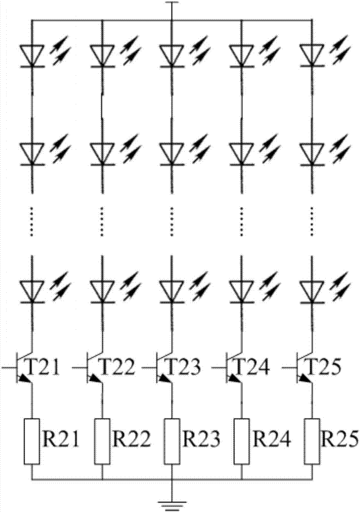
[0015] This embodiment provides a technical solution of an LED light-emitting driving circuit. In this technical solution, the bipolar junction transistor (Bipolar junction transistor, BJT) used for brightness control is an NPN type BJT, and the collector of the BJT is connected to the end of the last LED connected in series on the branch. The cathode is connected, the emitter of the BJT is connected to the current limiting resistor connected in series on the branch, and the other end of the current limiting resistor is grounded.
[0016] figure 2 A schematic circuit diagram of this embodiment is shown. see figure 2 , The LED light-emitting drive circuit consists of several branches connected in parallel. Several LEDs for light display, BJT T21-T25 for brightness control, and current limiting resistors R21-R25 for current limiting are connected in series on each branch.
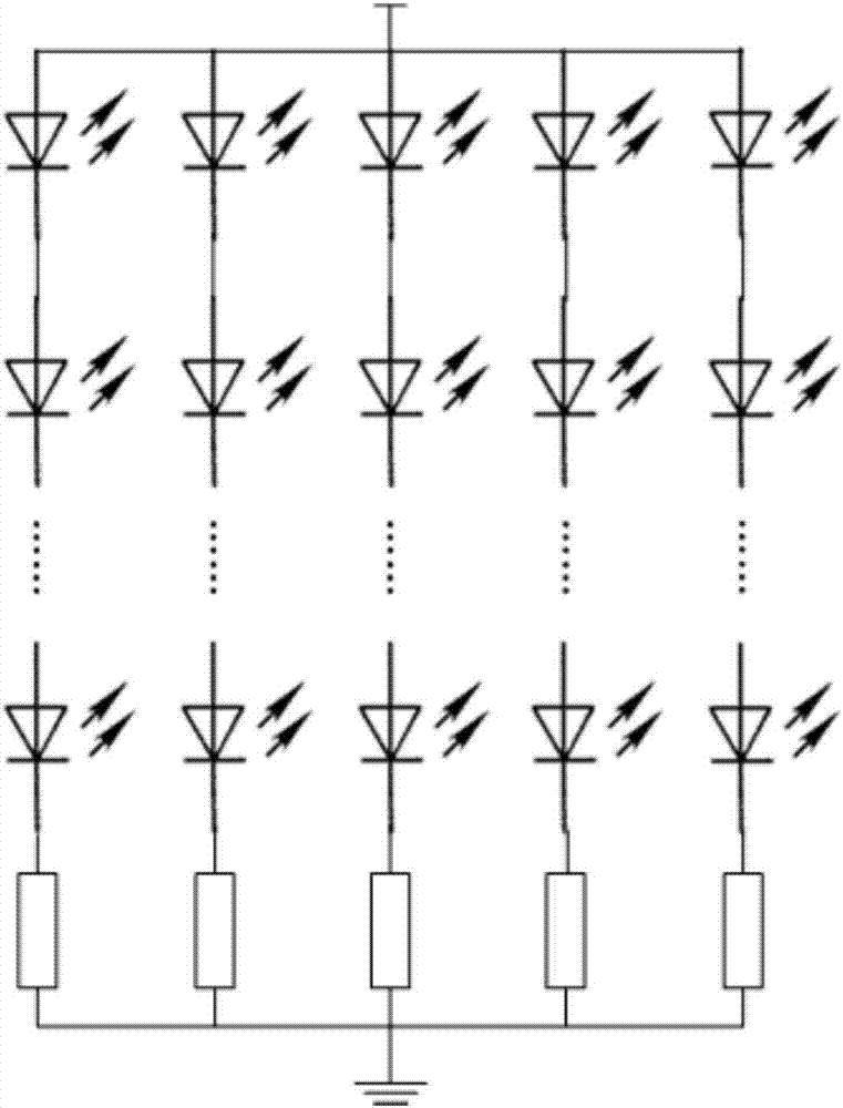
[0017] exist figure 1 In the LED light-emitting driving circuit shown, whether the LEDs connected i...
no. 2 example
[0023] This embodiment provides another technical solution of the LED light-emitting driving circuit. In this technical solution, the BJT used for brightness control is also an NPN type BJT, and the collector of the BJT is connected to the current limiting resistor connected in series on the branch, and the emitter of the BJT is grounded.
[0024] see figure 2 , the difference between this embodiment and the first embodiment of the present invention is that the series sequence of different elements on each branch will change. In the first embodiment of the present invention, the series sequence of components on each branch is: LED, BJT T21-T25, and current limiting resistors R21-R25. In this embodiment, the series sequence of components on each branch becomes: LED, current limiting resistors R31-R35, and BJT T31-T35.
[0025] The same thing as the first embodiment of the present invention lies in that the type of each BJT remains unchanged, and is still an NPN type BJT. In...
no. 3 example
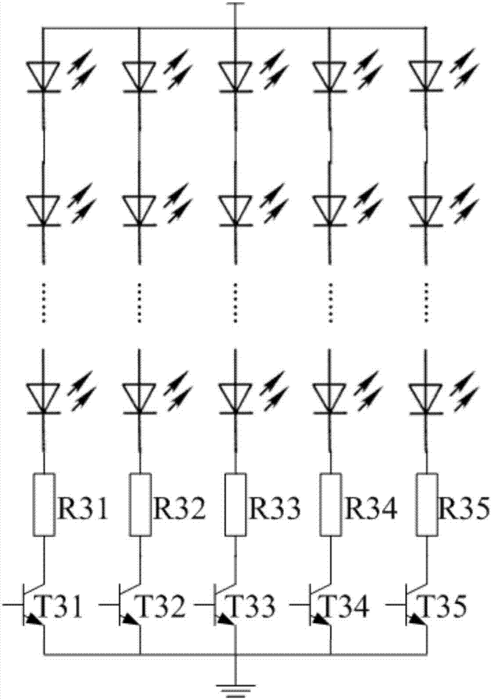
[0029] This embodiment provides another technical solution of the LED light-emitting driving circuit. In this technical solution, the type of BJT used for brightness control is no longer NPN type, but changed to PNP type. At the same time, the emitter of the BJT is connected to the current limiting resistor, the collector of the BJT is connected to the anode of the first LED in the LEDs connected in series on the branch, and the other end of the current limiting resistor is connected to the The drive voltage input end of the branch circuit is connected.
[0030] see image 3 The difference between this embodiment and the first embodiment of the present invention is that the type of BJT is changed from NPN type to PNP type. At the same time, the series sequence of different components on each branch has also changed. In the first embodiment of the present invention, the connection sequence of components on each branch is: LED, BJT T21-T25, and current limiting resistors R21-...
PUM
 Abstract
Description
Claims
Application Information
 - R&D
- Intellectual Property
- Life Sciences
- Materials
- Tech Scout
- Unparalleled Data Quality
- Higher Quality Content
- 60% Fewer Hallucinations
Browse by: Latest US Patents, China's latest patents, Technical Efficacy Thesaurus, Application Domain, Technology Topic, Popular Technical Reports.
© 2025 PatSnap. All rights reserved.Legal|Privacy policy|Modern Slavery Act Transparency Statement|Sitemap|About US| Contact US: help@patsnap.com