
Heat dissipation type power cabinet with targeted directional cooling function

A directional cooling and heat dissipation technology, applied in the cooling/ventilation of substation/switchgear, electrical components, substation/switch layout details, etc., can solve the problems of damage to electrical components of power cabinets, easy heat accumulation, low heat dissipation efficiency, etc. , to avoid shortening the service life, better heat dissipation, and simple structure.

Inactive Publication Date: 2017-10-20
深圳荣奥通网络信息技术有限公司
View PDF0 Cites 10 Cited by
  • Summary
  • Abstract
  • Description
  • Claims
  • Application Information

AI Technical Summary

Problems solved by technology

[0002] At present, with the rapid development of power technology, outdoor power cabinets, distribution cabinets and other cabinets for the installation of various electrical components have also been fully developed. There are a large number of power components inside. , the interior will generate a lot of heat, which will easily cause damage to the electrical components inside the power cabinet, resulting in undue power failure accidents and losses
[0003] Conventional power equipment dissipates heat by opening heat dissipation windows. Due to the poor air flow inside the power cabinet, the heat dissipation efficiency is low. Although the power cabinet equipped with a fan realizes air circulation and improves the heat dissipation efficiency, the cooling effect of the fan on the entire cabinet A kind of heat dissipation in the body, which is not targeted to the situation of excessive local heat production, and is prone to heat accumulation

Method used


Image

  • Heat dissipation type power cabinet with targeted directional cooling function
  • Heat dissipation type power cabinet with targeted directional cooling function
  • Heat dissipation type power cabinet with targeted directional cooling function

Examples


Embodiment Construction

[0018] The technical solution of this patent will be further described in detail below in conjunction with specific embodiments.

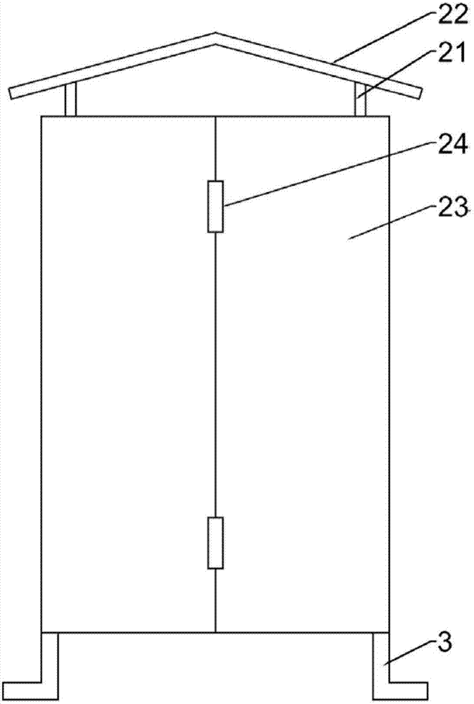
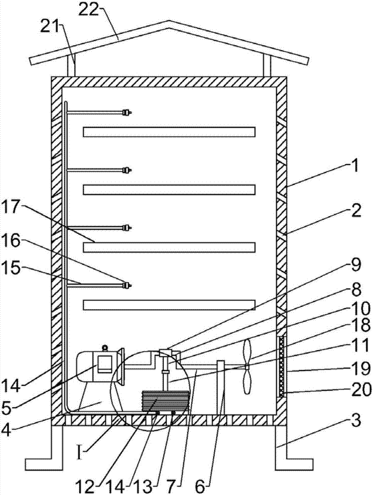
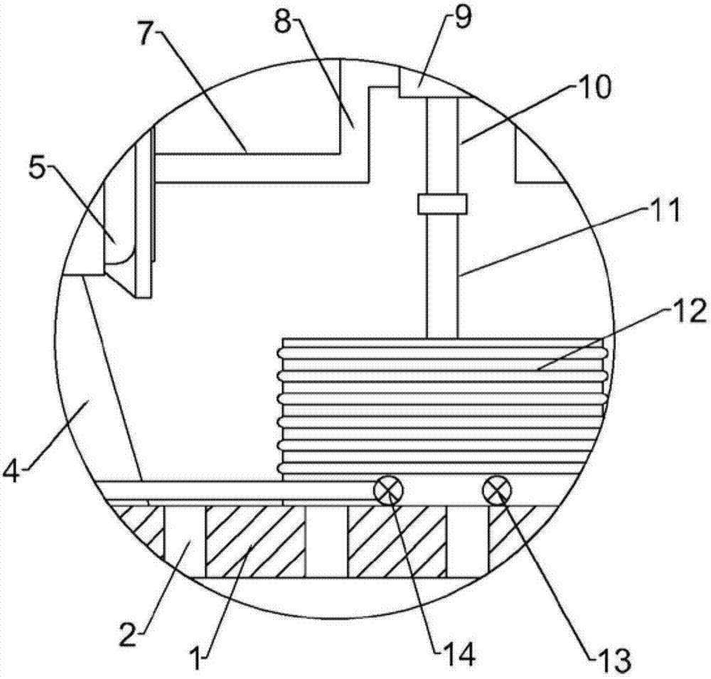
[0019] see Figure 1-3 , a heat-dissipating power cabinet with a targeted directional cooling function, comprising a cabinet body 1, a plurality of cooling holes 2 are opened on the outside of the cabinet body 1, and a motor base 4 is fixedly connected to the left side of the inside of the cabinet body 1, and the motor base 4 is fixedly connected with a motor 5 above, the inner bottom of the cabinet 1 is fixedly connected with a bearing seat 6, the upper part of the bearing seat 6 is rotatably connected with a rotating shaft 7, the rotating shaft 7 is connected with the motor 5, and the middle part of the rotating shaft 7 is fixedly connected There is a bell crank 8, and a transmission ring 9 is provided on the outer side of the bell crank 8. The lower side of the transmission ring 9 is fixedly connected with a first connecting rod 10, and the lowe...


PUM


Abstract

The invention discloses a heat-dissipating power cabinet with a targeted directional cooling function, which comprises a cabinet body, a plurality of cooling holes are opened on the outside of the cabinet body, a motor base is fixedly connected to the left side of the inside of the cabinet body, and the motor base is fixed on the top of the cabinet body. A motor is connected, and the bottom of the cabinet is fixedly connected with a bearing seat, and a rotating shaft is rotatably connected above the bearing seat, and the rotating shaft is connected with the motor. There is a transmission ring, the lower side of the transmission ring is fixedly connected with a first connecting rod, the lower side of the first connecting rod is rotationally and fixedly connected with a second connecting rod, and the center of the inside of the cabinet is fixedly connected with an inflating air bag. Compared with the prior art, the beneficial effect of the present invention is: the present invention is simple in structure, easy to use, can effectively dissipate heat to the power cabinet when the power cabinet is working, and the targeted heat dissipation makes the heat dissipation effect better, thus avoiding the power cabinet from being damaged by the temperature. It is worth promoting if the service life is shortened if it is too high.

Description

technical field [0001] The invention relates to a power cabinet, in particular to a heat dissipation type power cabinet with a targeted and directional cooling function. Background technique [0002] At present, with the rapid development of power technology, outdoor power cabinets, distribution cabinets and other cabinets for the installation of various electrical components have also been fully developed. There are a large number of power components inside. , a large amount of heat will be generated inside, which will easily cause damage to the electrical components inside the power cabinet, resulting in undue power failure accidents and losses. [0003] Conventional power equipment dissipates heat by opening heat dissipation windows. Due to the poor air flow inside the power cabinet, the heat dissipation efficiency is low. Although the power cabinet equipped with a fan realizes air circulation and improves the heat dissipation efficiency, the cooling effect of the fan on ...

Claims


Application Information

Patent Timeline
IPC IPC(8): H02B1/56
CPCH02B1/565
Inventor 胡永明
Owner 深圳荣奥通网络信息技术有限公司
Learn More