
Fault indicator

A fault indicator and sensor technology, applied in the field of power electronics, can solve problems such as the inability to monitor and record the temperature of cables, the inability to trace the time of fault occurrence, the failure to record the fault in time, and the failure to report in time if the temperature exceeds the limit. The effect of isolation and small energy loss

Active Publication Date: 2017-10-20
ZHEJIANG DAYOU IND CO LTD HANGZHOU SCI TECH DEV BRANCH CO +2
View PDF6 Cites 6 Cited by
  • Summary
  • Abstract
  • Description
  • Claims
  • Application Information

AI Technical Summary

Problems solved by technology

[0004] However, the third-generation fault indicator can only indicate whether a fault occurs and prompt after the fault occurs, and cannot track down the time of the fault and the record of repeated faults; and more importantly, it cannot monitor the temperature of the cable in real time. Monitoring and recording, no timely alarm in case of over-temperature

Method used


Image

  • Fault indicator
  • Fault indicator
  • Fault indicator

Examples


Embodiment Construction

[0031] The following will clearly and completely describe the technical solutions in the embodiments of the present invention in conjunction with the accompanying drawings in the embodiments of the present invention. Obviously, the described embodiments are only some of the embodiments of the present invention, not all of them. Based on the embodiments of the present invention, all other embodiments obtained by persons of ordinary skill in the art without making creative efforts belong to the protection scope of the present invention.

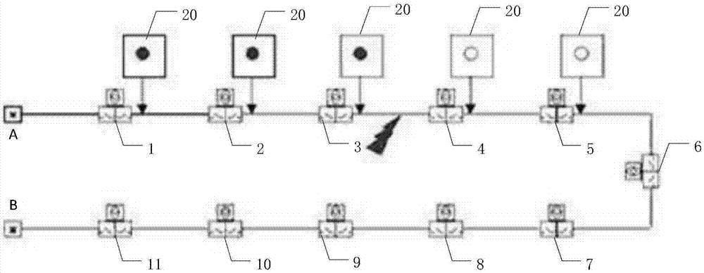
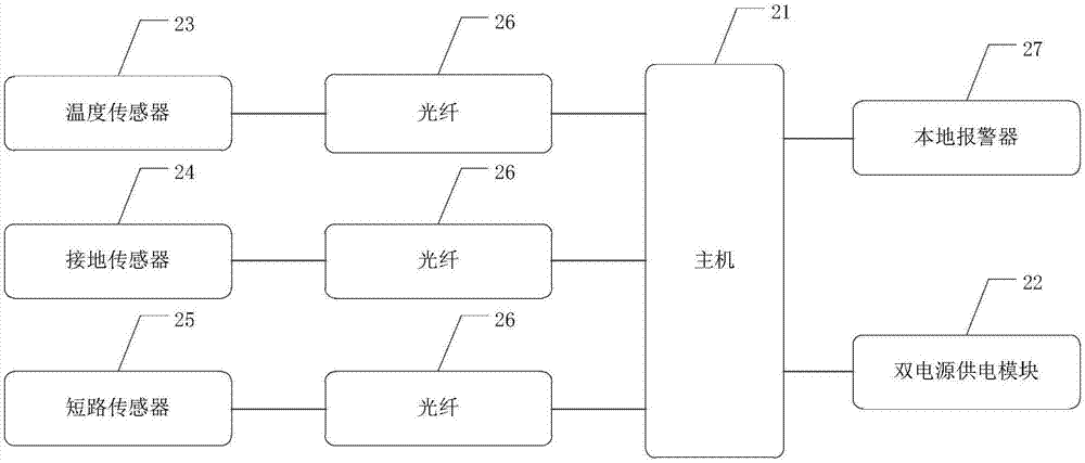
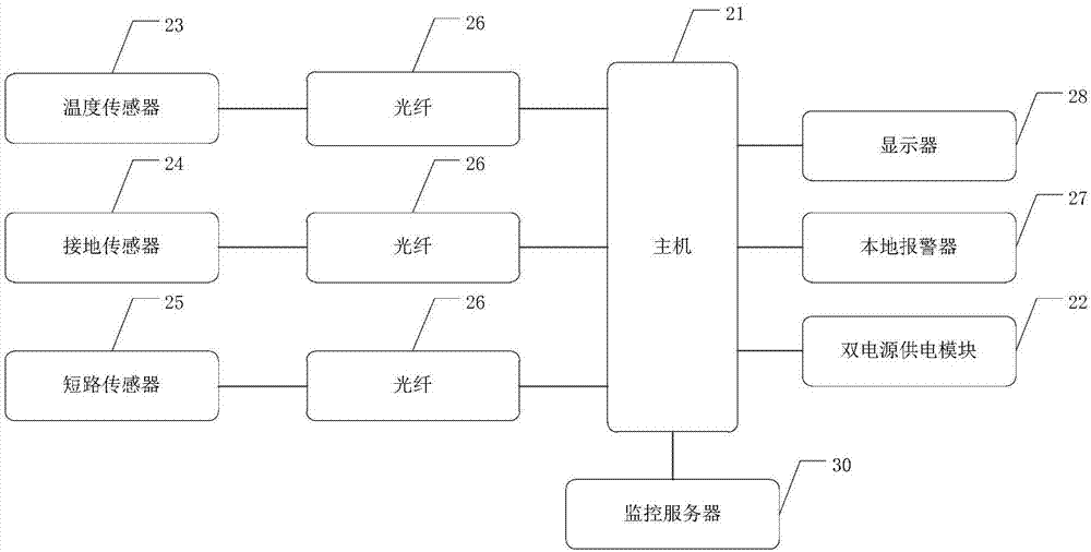
[0032] The core of the invention is to provide a fault indicator, which can monitor and record the temperature of the cable in real time, and give an alarm in time when a cable fault is detected. In addition, the transmission of the collected signal through the optical fiber has the advantage of strong anti-interference, and the reliability of the fault indicator is improved through the power supply of the dual power supply module.

[0033] In ...


PUM


Abstract

The invention discloses a fault indicator which collects the temperature signal of a cable, a grounding fault signal and a short-circuit fault signal and transmits the signals to a host computer through an optical fiber for signal analysis. When the host computer judges that the temperature signal exceeds a preset value or a grounding phenomenon or short circuit phenomenon appears, a local alarm connect with the host computer is turned on to carry out alarm prompt. According to the invention, the fault indicator can determine whether a cable fails in time; the staff can use the local alarm situation to quickly determine a line fault section and find a fault point; in addition, the collected signals are transmitted through the optical fiber, which realizes photoelectricity isolation and effectively solves the insulation problem; the signals in a transmission process have small energy loss and are not susceptible to external interference; the host computer is powered by a dual power supply module; the redundancy is improved; and power supply is more reliable.

Description

technical field [0001] The invention relates to the technical field of power electronics, in particular to a fault indicator. Background technique [0002] In the ring network power distribution system, especially in the system that uses a large number of ring network load switches, if a short-circuit fault or a ground fault occurs in the lower-level power distribution network system, the upper-level power supply system must be within the specified Time to break, in order to prevent major accidents. After the breaking protection occurs, all systems belonging to this level of network will be blacked out. Maintenance personnel need to quickly find the faulty section, disconnect the faulty section, and restore the power supply of the non-faulty section in time. In this way, it can save a lot of time to find the faulty part, and also reduce the power outage time and scope, and bring a win-win effect to the customer and the power supply system. [0003] In order to quickly det...

Claims


Application Information

Patent Timeline
IPC IPC(8): G05B19/042G01D21/02
CPCG01D21/02G05B19/042G05B19/0423G05B2219/21014G05B2219/21162G05B2219/25174G05B2219/25197
Inventor 何春林戚佳金郑正仙严性平陈潘霞蒋燕萍
Owner ZHEJIANG DAYOU IND CO LTD HANGZHOU SCI TECH DEV BRANCH CO
Learn More