Al technical title is built by PatSnap Al team. It summarizes the technical point description of the patent document.
A shrinking device and sample technology, applied in the field of solid sample shrinking device, can solve the problems of dirty air in the laboratory, unfavorable respiratory health of experimenters, and reduction of sample volume, etc.
Pending Publication Date: 2017-10-20
浙江云广检测技术有限公司
View PDF10 Cites 1 Cited by
Summary
Abstract
Description
Claims
Application Information
AI Technical Summary
This helps you quickly interpret patents by identifying the three key elements:
Problems solved by technology
Method used
Benefits of technology
Problems solved by technology
[0002] Dividing is the most critical procedure of sample preparation. The purpose is to reduce the amount of sample. The division of samples can be carried out by mechanical or manual methods. The sampling volume of solid samples in laboratory testing is relatively large, while the actual testing uses The amount of samples is relatively small, so it is particularly important to obtain representative samples for the division of samples. The existing division method is the quartering method, which uses manual division, and the uniformity of division is poor, and powdery samples are easy to float. , resulting in dirty air in the laboratory, which is not good for the respiratory health of the experimenters
Method used
Image
Click on the blue label to locate the original text in one second.
Reading with bidirectional positioning of images and text.
Examples
Embodiment Construction
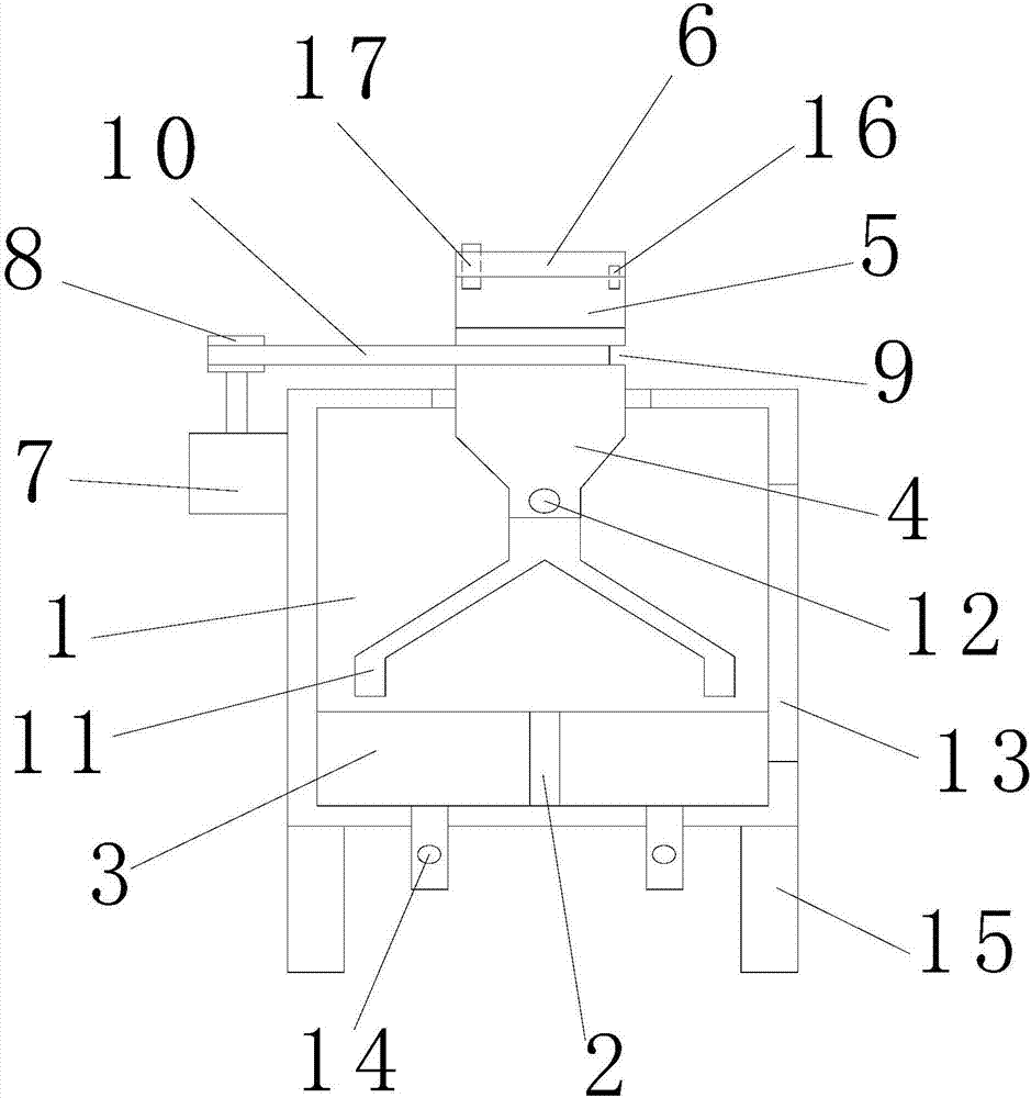
[0017] refer to figure 1 , a kind of solid sample shrinkage device of the present invention, comprises outer cylinder 1, dividing plate 2, receiving chute 3, lower hopper 4, standard sieve 5, cover plate 6, motor 7, belt pulley 8, belt groove 9, belt 10 , a material distribution inclined pipe 11, a feeding valve 12, an inspection door 13, a discharge valve 14 and a support leg 15, and the inner bottom of the outer cylinder 1 is fixed with a plurality of partition plates 2 along the radial direction to separate the outer cylinder 1 The bottom of the inside is divided into a plurality of receiving troughs 3 with equal areas. The center position of the upper part of the outer cylinder 1 can be rotated to be provided with a vertically arranged lower hopper 4, and the upper part of the lower hopper 4 is fixedly equipped with a standard screen. 5. The upper part of the standard sieve 5 is rotatably provided with a horizontally arranged cover plate 6 through the rotating shaft 16, an...
PUM
Abstract
The invention discloses a solid sample division device, comprising an outer barrel, partition plates, receiving troughs, a feeding hopper, a standard screen, a cover plate, a motor, a pulley, a belt groove, a belt, oblique distribution pipes, a feeding valve, a maintenance door, discharge valves, and support legs; the partition plates are radially fixed at the inner bottom of the outer barrel and divide the inner bottom of the outer barrel into a plurality of receiving troughs in equal area, the feeding hopper is vertically and rotationally arranged in the upper center of the outer barrel, the standard screen is fixed to the upper portion of the feeding hopper, the cover plate is horizontally and rotationally arranged at the upper portion of the standard screen, a motor having a vertical spindle is fixed to the outer side of the outer barrel, and the pulley is fixed to the spindle of the motor. Compared with the prior art, the solid sample division device has the advantages that solid samples can be divided quickly and efficiently, division uniformity for the solid samples is improved, sample drifting is effectively avoided, and experimental operations are greatly facilitated.
Description
【Technical field】 [0001] The invention relates to the technical field of shrinkage devices, in particular to a solid sample shrinkage device. 【Background technique】 [0002] Dividing is the most critical procedure of sample preparation. The purpose is to reduce the amount of sample. The division of samples can be carried out by mechanical or manual methods. The sampling volume of solid samples in laboratory testing is relatively large, while the actual testing uses The amount of samples is relatively small, so it is particularly important to obtain representative samples for the division of samples. The existing division method is the quartering method, which uses manual division, and the uniformity of division is poor, and powdery samples are easy to float. , resulting in dirty air in the laboratory, which is detrimental to the respiratory health of the experimenters. 【Content of invention】 [0003] The purpose of the present invention is to solve the problems in the pri...
Claims
Application Information
Patent Timeline
Application Date:The date an application was filed.
Publication Date:The date a patent or application was officially published.
First Publication Date:The earliest publication date of a patent with the same application number.
Issue Date:Publication date of the patent grant document.
PCT Entry Date:The Entry date of PCT National Phase.
Estimated Expiry Date:The statutory expiry date of a patent right according to the Patent Law, and it is the longest term of protection that the patent right can achieve without the termination of the patent right due to other reasons(Term extension factor has been taken into account ).
Invalid Date:Actual expiry date is based on effective date or publication date of legal transaction data of invalid patent.