Leaking stoppage method for gas pipeline and device implementing method
A technology of gas pipeline and plugging method, which is applied in the direction of pipe components, pipes/pipe joints/pipe fittings, mechanical equipment, etc., and can solve the problems of secondary leakage, loosening, and weakening of the compression effect of sealing briquettes, so as to achieve difficult secondary leakage. Leakage and plugging work is convenient, and the effect of ensuring leakage work is up to standard
- Summary
- Abstract
- Description
- Claims
- Application Information
AI Technical Summary
Problems solved by technology
Method used
Image
Examples
Embodiment 1
[0038] Embodiment 1: a kind of plugging method of gas pipeline, refer to figure 1 with figure 2 As shown, the method includes the following steps in turn:
[0039] a. The emergency repair personnel of the gas company arrive at the scene as soon as possible, prepare fire extinguishers, explosion-proof fans, etc., use experience or equipment to find out the specific leak point of the gas pipeline 1 according to the site situation, and clean up the anti-corrosion substances, rust and impurities on the pipeline around the leak point Clean, so that the surface of the gas pipeline 1 around the leakage point is smooth;
[0040]b. According to the diameter of the gas pipeline 1, select a leak-stopping device that matches the diameter of the gas pipeline 1, wrap the soft body 2 on the leak-stopping device on the gas pipeline 1 in a ring shape, and The first end portion 201 and the second end portion 202 are fixed together, the soft body 2 and the gas pipeline 1 are sleeved relativel...
Embodiment 2
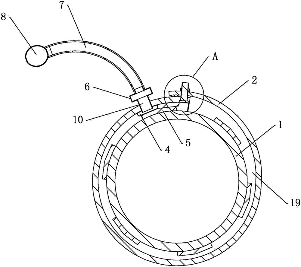
[0043] Embodiment 2: a leak plugging device, used to realize the above embodiment 1, such as figure 1 As shown, it includes a soft body 2 wrapped around the gas pipeline 1. The soft body 2 is made of soft material and can be curled and bent to form a ring. The two ends of the soft body 2 are the first ends respectively. part 201 and second end part 202, after the soft body 2 is fastened and wound on the gas pipeline 1, the first end part 201 and the second end part 202 are bonded and fixed by glue 3, and the glue 3 adopts anti-corrosion Sexual glue 3, preferably acrylic type adhesive, acrylic type adhesive has adhesiveness and anti-corrosion, adopts the mode of coating to fix and bond the first end 201 and the second end 202, can avoid the second The connection between the first end 201 and the second end 202 is affected by the corrosion of corrosive substances, and the bonded soft body 2 is firmly attached to the outer circumferential surface of the gas pipeline 1 .
[0044]...
Embodiment 3
[0048] Embodiment 3: a kind of plugging device, the difference with embodiment 2 is, such as image 3 with Figure 4 As shown, the first end 201 is provided with a through hole 14 and a nut 13 penetrating through the inner and outer surfaces of the first end 201, and the second end 202 is fixedly connected with a bolt 12, and the bolt 12 is connected to the nut 13 after passing through the through hole 14. Threaded fixing to realize the fixing of the first end 201 and the second end 202; the inner surface of the first end 201 facing the gas pipeline 1 is fixedly connected with an inclined first ratchet 15, and the first ratchet 15 is from top to bottom The bottom is gradually inclined to the right, and the outer surface of the first end 201 is fixedly connected with an inclined second ratchet 16, the inclination direction of the second ratchet 16 is consistent with the inclination direction of the first ratchet 15, and the first ratchet The first ratchet 15 and the second rat...
PUM
 Abstract
Description
Claims
Application Information
 - Generate Ideas
- Intellectual Property
- Life Sciences
- Materials
- Tech Scout
- Unparalleled Data Quality
- Higher Quality Content
- 60% Fewer Hallucinations
Browse by: Latest US Patents, China's latest patents, Technical Efficacy Thesaurus, Application Domain, Technology Topic, Popular Technical Reports.
© 2025 PatSnap. All rights reserved.Legal|Privacy policy|Modern Slavery Act Transparency Statement|Sitemap|About US| Contact US: help@patsnap.com


