Power cable device

A technology for power cables and bases, applied in the field of power cable installations, can solve the problems of labor and time consumption, reduced corporate profits, low efficiency, etc., and achieve the effect of reducing manual operations and improving work efficiency

Inactive Publication Date: 2017-10-20
何纪全
View PDF10 Cites 0 Cited by
  • Summary
  • Abstract
  • Description
  • Claims
  • Application Information

AI Technical Summary

Problems solved by technology

Then it is necessary to remove the coiled wire from the coiled wire drum. The process of unloading the drum-shaped wire is more complicated, and then replace the new wire drum to re-coil, and then start the next round of winding. This method is more efficient. It is relatively low and requires more manpower and time, which will affect the overall wire rolling process and reduce the profit of the enterprise.

Method used


Image

  • Power cable device
  • Power cable device
  • Power cable device

Examples


Embodiment Construction

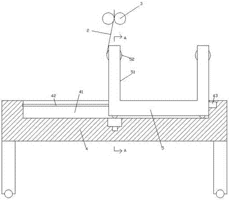
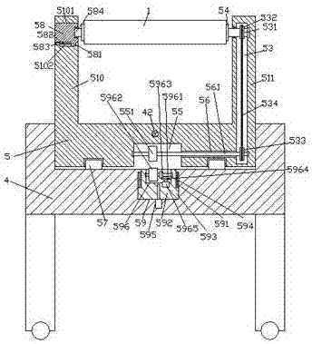
[0024] like Figure 1-Figure 6 As shown, a power cable device of the present invention includes a base 4 and a clamp 3 arranged above the top of the base 4 and opposite to the left and right. The bottom of the column 401 is provided with casters 402, the base 4 is provided with a first guide groove 41, and the inside of the first guide groove 41 is slidingly fitted to connect the base 5, and the middle position of the bottom of the first guide groove 41 is A first sliding groove 59 is provided, and the front and rear sides of the first sliding groove 59 are symmetrically provided with a second guiding groove 591. The first sliding groove 59 is provided with a first sliding block 592. The front and rear sides of the bottom of the first sliding block 592 are respectively provided with first guide blocks 593 extending into the second guide grooves 591 on the front and rear sides, and the middle part of the end face of the bottom of the base 5 is provided with a slot extending lef...


PUM


Abstract

The invention discloses a power cable device. The power cable device comprises a base and clamps which are arranged above the top of the base and are arranged oppositely in the left-to-right direction; foot pillars are fixedly mounted at the bottom of the base; a caster wheel is arranged at the bottom of each of the foot pillars; a first guide groove is formed in the base; the interior of the first guide groove is in sliding connection with a bottom seat in a matched manner; a first sliding groove is formed in the central position of the bottom of the first guide groove; second guide grooves are symmetrically formed in the front side and the rear side of the first sliding groove; a first sliding block is arranged in the first sliding groove; and first guide blocks which penetrate into the second guide grooves in the front side and the rear side are arranged on the front side and the rear side of the first sliding block separately. The power cable device is simple in structure, the bottom seat can be controlled to move left and right automatically, so that support frame members on the left side and the right side can switch between the work of winding an electric wire and the work of dismounting and replacing an electric wire winding drum, the convenience in mounting and dismounting is improved, and an electric wire winding process is not affected.

Description

technical field [0001] The invention relates to the technical field of power cables, in particular to a power cable device. Background technique [0002] After the electric wire is produced, processed and formed, the electric wire needs to be rolled up to facilitate storage and transportation. The existing electric wire rolling machine includes two relatively movable support frames, a winding wire shaft arranged on the two support frames, and a The winding wire barrel on the winding wire shaft and the motor that drives the winding wire shaft to rotate; when winding the wire, first fix the end of the wire on the winding wire drum, turn on the motor, and perform the wire winding action. Then it is necessary to remove the rolled electric wire from the reel. The process of unloading the cylindrical electric wire is more complicated, and then replace the new electric reel to rewind, and then start the next round of winding. This method is more efficient. It is relatively low, an...

Claims


Application Information

Patent Timeline
IPC IPC(8): B65H67/04B65H54/74B65H54/54B65H54/72
CPCB65H67/0411B65H54/54B65H54/72B65H54/74B65H67/0417B65H2701/34
Inventor 何纪全
Owner 何纪全
Why Eureka
Try Eureka