Cavity space compensable and adjustable upper valve body and pneumatic valve with upper valve body applied
A compensation adjustment, chamber technology, applied in the direction of control valve, air release valve, lift valve, brake, etc., can solve the problem that the braking ability of pneumatic valve cannot cope with the working environment, the braking ability is not improved by compensation, and the braking effect is excellent. , to achieve the effect of easy maintenance or maintenance, good driving experience and obvious effect
- Summary
- Abstract
- Description
- Claims
- Application Information
AI Technical Summary
Problems solved by technology
Method used
Image


Examples
Embodiment 1
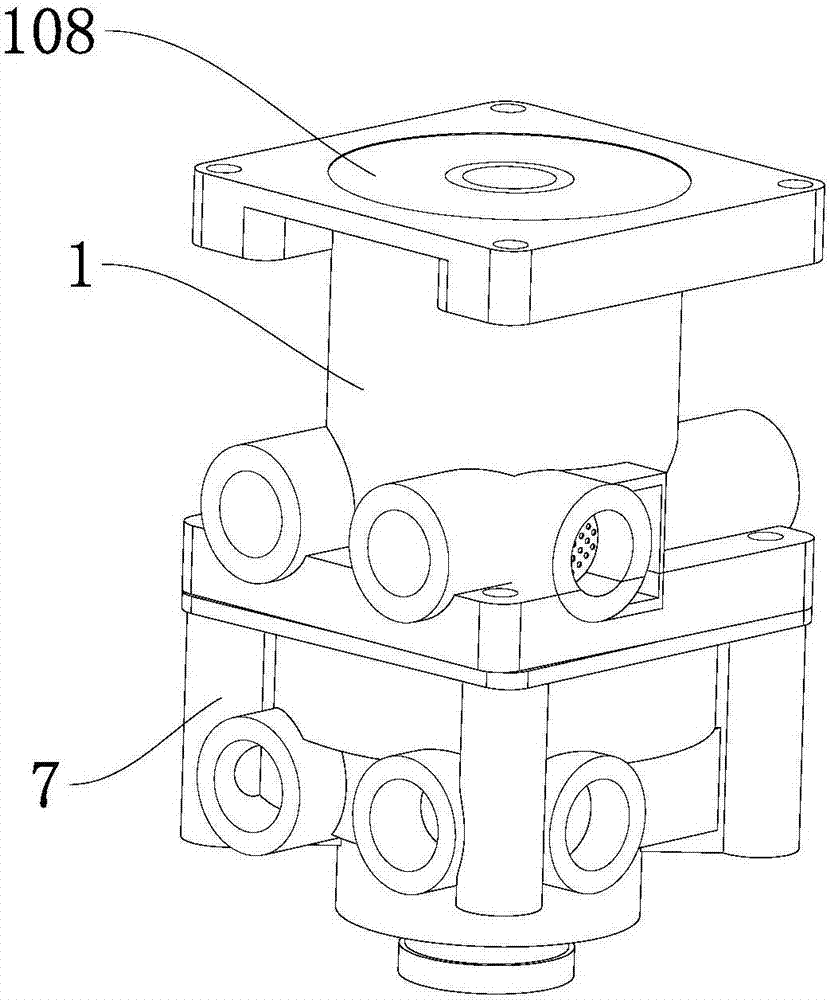
[0058] Such as figure 1 , figure 2 , image 3 As shown, this embodiment discloses an upper valve body whose chamber space can be compensated and adjusted. Upper valve pneumatic chamber 103; upper chamber 101 is provided with a valve core, upper valve chamber 102 is provided with upper valve chamber seal 4, upper valve gasket 401 located on the upper part of upper valve chamber seal 4, sleeved on The upper valve gasket 6 on the chamber seal, the upper valve spring 5 placed between the chamber seal and the upper valve gasket 6, the upper valve stopper 109 placed under the upper valve gasket 6, the upper valve pneumatic chamber 103 is located The bottom of the upper case 1.
[0059] Preferably, both the upper chamber 101 and the upper valve air storage chamber 102 are cylindrical chambers, and the valve core is cylindrical in shape.
[0060] The spool is composed of a piston sleeve 2 and a driving piston 3; the piston sleeve 2 is connected to the upper housing 1 and a first ...
Embodiment 2
[0104] This embodiment discloses a pneumatic valve. The components and connection methods of the pneumatic valve in this embodiment are the same as those in Embodiment 1, the difference lies in:
[0105] In this embodiment, the upper valve body adopts a valve core with a different structure.
[0106] Such as Figure 5 , Figure 6 As shown, for the spool in this embodiment, the piston sleeve 2 is a sleeve with a "mountain" shape in the longitudinal section, and the piston sleeve 2 is fixedly connected with the upper chamber 101; the inside of the piston sleeve 2 forms a second cavity with the driving piston 3 , the second cavity is provided with a return spring 301, the upper end of the return spring 301 is connected to the upper section of the driving piston 3 and the lower end is connected to the piston sleeve 2; the outer wall of the piston sleeve 2 and the inner wall of the upper housing 1 form a third cavity with a closed upper end and an open lower end body, the third c...
Embodiment 3
[0110] This embodiment discloses a pneumatic valve. The components and connection methods of the pneumatic valve in this embodiment are the same as those in Embodiment 1, the difference lies in:
[0111] In this embodiment, the upper valve body adopts a valve core with a different structure.
[0112] Such as Figure 7 , Figure 8 As shown, the spool in this embodiment, the piston sleeve 2 is a sleeve with a "mountain" shape in the longitudinal section, the piston sleeve 2 is slidably connected with the upper chamber 101, and the inside of the piston sleeve 2 forms a second cavity with the driving piston 3 , the second cavity is provided with a return spring 301, the upper end of the return spring 301 is connected to the upper section of the driving piston 3 and the lower end is connected to the piston sleeve 2; the outer wall of the piston sleeve 2 is provided with a fourth cavity with a closed upper end and an open lower end, the fourth cavity There is a compensating adjust...
PUM
 Abstract
Description
Claims
Application Information
 - Generate Ideas
- Intellectual Property
- Life Sciences
- Materials
- Tech Scout
- Unparalleled Data Quality
- Higher Quality Content
- 60% Fewer Hallucinations
Browse by: Latest US Patents, China's latest patents, Technical Efficacy Thesaurus, Application Domain, Technology Topic, Popular Technical Reports.
© 2025 PatSnap. All rights reserved.Legal|Privacy policy|Modern Slavery Act Transparency Statement|Sitemap|About US| Contact US: help@patsnap.com