
Fast leaking stoppage device and leaking stoppage method for strongly-permeable and loose stratum

A plugging method and strong permeable technology, applied in construction, infrastructure engineering and other directions, can solve the problems of not being able to meet the requirements of anti-seepage plugging, high operating level requirements, and the diffusion range of blocked pipes, so as to achieve fast and effective plugging. Leakage effect, good connectivity, large void effect

Active Publication Date: 2017-10-17
SINOHYDRO BUREAU 8 CO LTD
View PDF6 Cites 1 Cited by
  • Summary
  • Abstract
  • Description
  • Claims
  • Application Information

AI Technical Summary

Problems solved by technology

For the seepage of strong permeable and loose strata, it is more effective and simple to adopt double-liquid grouting technology to prevent seepage and plugging. The existing relatively advanced technologies mainly include sleeve valve pipe double-liquid grouting technology and buried pipe lifting rod pure pressure double-liquid Grouting technology, the common feature of these two double-liquid grouting technologies is that a single grouting pipe is used in the hole, and the cement grout and water glass grout need to be mixed in the grouting bucket, nozzle or pipe. The level requirements are very high, and a little carelessness can easily cause defects such as pipe blockage or diffusion range that cannot meet the requirements of anti-seepage and plugging.

Method used


Image

  • Fast leaking stoppage device and leaking stoppage method for strongly-permeable and loose stratum
  • Fast leaking stoppage device and leaking stoppage method for strongly-permeable and loose stratum
  • Fast leaking stoppage device and leaking stoppage method for strongly-permeable and loose stratum

Examples


Embodiment Construction

[0035] The present invention will be described in further detail below in conjunction with the accompanying drawings and specific embodiments.

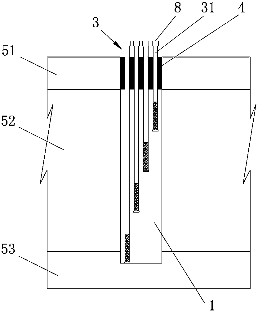
[0036] Such as Figure 1 to Figure 3 As shown, the rapid plugging device for highly permeable and loose formations of this embodiment includes a drilling tool 2 for drilling the grouting hole 1, a combined floral tube 3, and a hole for the combined floral tube 3 to be inserted into the grouting hole 1 to the grouting hole 1 The sealing plug body 4 for sealing the mouth, the combined flower tube 3 includes at least one group of grouting tube groups, each group of grouting tube groups includes two grouting tubes 31, the lower end of the grouting tubes 31 is closed, and the upper end extends out of the hole of the grouting hole 1 Grouting eyes 311 are provided on the lower end surface or the lower peripheral surface of the grouting pipe 31, and the heights of the lower end surfaces of all the grouting pipes 31 in the grouting hole 1 are ...


PUM


Abstract

The invention discloses a fast leaking stoppage device and leaking stoppage method for a strongly-permeable and loose stratum. The device comprises a drilling tool for drilling a grouting hole, a combined floral pipe and a sealing and stopping body for sealing the opening of the grouting hole after the combined floral pipe is inserted in the grouting hole; the combined floral pipe comprises at least one grouting pipe group, each grouting pipe group comprises two grouting pipes, the opening of the lower end of each grouting pipe is sealed, the upper end of each grouting pipe extends out of the opening of the grouting hole, the end face or the peripheral face of the lower end of each grouting pipe is provided with a grouting floral hole, and the heights of the lower end faces of all the grouting pipes in the combined floral pipe are all different. The method comprises the steps that the grouting hole is drilled and the combined floral pipe is inserted in the grouting hole; quick-solidification cement mortar is adopted to pour the opening of the grouting hole; each grouting pipe is filled with stabilized cement-clay slurry; one grouting pipe in each grouting pipe group is grouted with cermet slurry and the other grouting pipe is grouted with water glass slurry, so that the two kinds of slurry are mixed to fill the gap in the strongly-permeable and loose stratum and fast seal and stop a leakage stoppage channel.

Description

technical field [0001] The invention relates to the technical field of grouting construction, in particular to a fast leak-stopping device and a leak-stopping method for strong water-permeable loose formations. Background technique [0002] In engineering construction, highly permeable loose strata mainly refer to soil layers with high permeability coefficients such as earth-rock accumulations, original sand and pebble overlays, earth-rock filling layers, etc. Relatively waterproof. For the seepage of strong permeable and loose strata, it is more effective and simple to adopt double-liquid grouting technology to prevent seepage and plugging. The existing relatively advanced technologies mainly include sleeve valve pipe double-liquid grouting technology and buried pipe lifting rod pure pressure double-liquid Grouting technology, the common feature of these two double-liquid grouting technologies is that a single grouting pipe is used in the hole, and the cement grout and wat...

Claims


Application Information

Patent Timeline
IPC IPC(8): E02D19/16E02D15/04
CPCE02D15/04E02D19/16E02D2250/0023
Inventor 郭国华邹爱明杨志清杨齐
Owner SINOHYDRO BUREAU 8 CO LTD
Learn More