Cordwood temporary support base structure and construction method thereof

A temporary support and construction method technology, applied in construction, bridge construction, bridges, etc., can solve the problems of inability to preheat resistance lines, long construction period, delayed construction period, etc. The effect of high installation efficiency

Active Publication Date: 2017-10-17
ZHENGZHOU MUNICIPAL ENG CORP
View PDF14 Cites 0 Cited by
  • Summary
  • Abstract
  • Description
  • Claims
  • Application Information

AI Technical Summary

Problems solved by technology

[0004] At present, the construction methods of temporary supports for continuous girder piers mainly include the following: one is to use all-concrete temporary supports. In concrete, there is no isolation layer between the temporary support and the pier column and beam body, so the entire concrete temporary support needs to be chiseled out during demolition. Generally, the concrete grade of the temporary support exceeds C40, and it is time-consuming and labor-intensive to chisel out , there are also situations such as delays in the construction period
The second is to use sulfur mortar temporary support, which requires careful installation of the lead wires and sulfur mortar in the support structure during operation. It is easy to break the resistance wire during installation, which leads to the temporary dismantling of the pier top in the later stage. When the support is used, the resistance wire cannot be preheated, so that the sulfur mortar cannot be dissolved, and the role of the dissolved layer cannot be achieved. When dismantling, it is necessary to chisel out the entire temporary support on the top of the concrete pier, which takes a lot of time and has a long construction period
The structure of the existing and temporary supports cannot be reused, and a large amount of waste will be formed after the bridge construction is completed and dismantled, which not only wastes materials, but also pollutes the environment

Method used


Image

  • Cordwood temporary support base structure and construction method thereof
  • Cordwood temporary support base structure and construction method thereof
  • Cordwood temporary support base structure and construction method thereof

Examples


Embodiment Construction

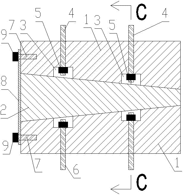
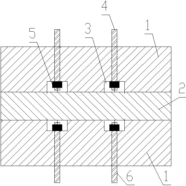
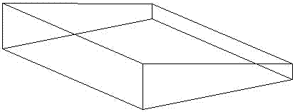
[0034] Such as Figure 1 to Figure 8 As shown, the building block type temporary support structure of the present invention includes a beam body 10, a pier 11 and a support unit assembled from 2 A standard blocks 1 and 1 B standard block 2, and the length and width of the A standard block 1 Both are the same length and width as the B standard block 2; the vertical section of the A standard block 1 is a right-angled trapezoid, and the vertical section of the B standard block 2 is an isosceles trapezoid; the shorter bottom of the trapezoid is the upper bottom and the longer The bottom is the lower bottom; four bolt grooves 3 are evenly arranged in the middle of the slope of A standard block 1, and each bolt groove 3 is connected with a vertical light hole that runs through A standard block 1, and the other opening of the vertical light hole is located at A The plane where the right-angled side of the section of standard block 1 is located; the plane where the upper bottom of A s...


PUM


Abstract

The invention discloses a cordwood temporary support base structure. The structure comprises a beam body, a bridge pier and a support base unit, a rectangular support base unit is assembled from two A standard blocks and a B standard block, and the inclined planes of two sides of the cross section of B standard block are attached to the inclined plane of the upper A standard block and the inclined plane of the lower A standard block respectively; beam body connecting bolts are arranged in a vertical unthreaded hole of the A standard block which is located above the B standard block in a penetrating mode, and fixing nuts which are connected to the beam body connecting bolts in a threaded mode are arranged in bolt grooves; the beam body connecting bolts are upwards and fixedly connected with the beam body, and bridge pier connecting bolts are downwards and fixedly connected with the bridge pier; the beam body and the bridge pier are fixedly and integrally connected through a plurality of support base units. The invention further discloses a construction method of the cordwood temporary support base structure. The disassembling efficiency of the temporary support base is greatly improved compared with the prior art, and the construction period is shortened; no waste generates after the temporary support base is disassembled, the environment is not polluted, and the use cost is saved.

Description

technical field [0001] The invention relates to the technical field of bridge construction, in particular to a temporary support structure and a construction method thereof. Background technique [0002] With the rapid development of road traffic, bridges have been more widely used. Many bridges adopt the method of cantilever pouring concrete continuous beams to meet the requirements of the height and width of the spanning structure. [0003] In the process of bridge construction, the bottom of the beam body of the bridge and the piers need to be fixedly connected together to ensure the stability of the construction process. After the construction is completed, it is necessary to convert the girder body and the pier into a hinge joint, so that the girder body can have a certain displacement space during the use of the bridge, so that the girder body can resolve the external force through a small displacement and improve the adaptability of the bridge and service life. [0...

Claims


Application Information

Patent Timeline
Patent Type & Authority Applications(China)
IPC IPC(8): E01D21/00E01D19/04
CPCE01D19/04E01D21/00
Inventor 吴纪东王明远光军伟张双梅陈波于化龙梁宪荣
Owner ZHENGZHOU MUNICIPAL ENG CORP
Why Eureka
Try Eureka