Charging structure for electric vehicle

A charging structure and electric vehicle technology, applied in the direction of electric vehicle charging technology, electric vehicles, charging stations, etc., can solve the problems of short service life, messy, long charging cables, etc., achieve stable operation, simple device structure, and convenient use Effect

Active Publication Date: 2017-10-17
ANHUI DYNAMIC POWER
View PDF4 Cites 7 Cited by
  • Summary
  • Abstract
  • Description
  • Claims
  • Application Information

AI Technical Summary

Problems solved by technology

Nowadays, people are also aware of this problem. Therefore, people pay more and more attention to new energy vehicles. New energy vehicles include pure electric vehicles, extended-range electric vehicles, hybrid vehicles, fuel cell electric vehicles, hydrogen engine vehicles, and other new energy vehicles. Energy vehicles, etc. Pure electric vehicles are vehicles that use a single battery as the energy storage power source. Pollution, the batteries in pure electric vehicles generally need power supply piles to charge. In traditional power supply piles, the charging cables are long. When not in use, the charging cables are often exposed outside the power supply piles. It is to drag and drop everywhere, which not only gives people a messy feeling, but also is easy to be run over by cars and trampled by pedestrians. Therefore, the service life is short and there is also a risk of electricity safety

Method used


Image

  • Charging structure for electric vehicle
  • Charging structure for electric vehicle
  • Charging structure for electric vehicle

Examples


Embodiment Construction

[0020] All features disclosed in this specification, or steps in all methods or processes disclosed, may be combined in any manner, except for mutually exclusive features and / or steps.

[0021] Any feature disclosed in this specification (including any appended claims, abstract and drawings), unless expressly stated otherwise, may be replaced by alternative features which are equivalent or serve a similar purpose. That is, unless expressly stated otherwise, each feature is one example only of a series of equivalent or similar features.

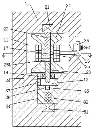
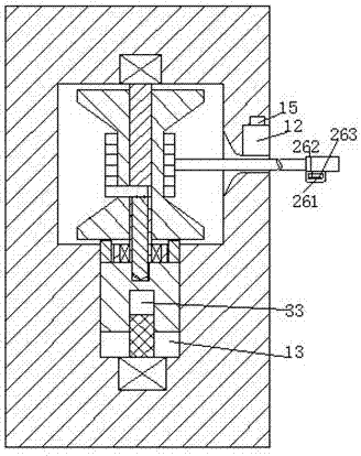
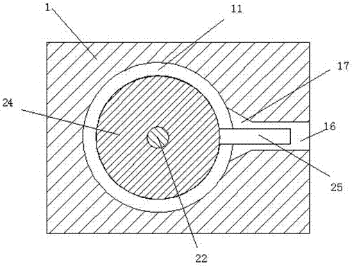
[0022] like Figure 1-3 As shown, a charging structure for an electric vehicle according to the present invention includes a main body 1 of a power supply pile. A rotating groove 11 is arranged in the main body 1 of the power supply pile. Between the retractable groove 12 and the rotating groove 11, there is a connected extending groove 16, and the upper end wall of the retractable groove 12 is provided with a suspension groove 15, and a rota...


PUM


Abstract

A charging structure for an electric vehicle comprises a power supplying pile body, a rotating groove is formed in the power supplying pile body, a storage groove is formed in the right end surface of the power supplying pile body, a suspension groove is formed in the upper end wall of the storage groove, and a rotating motor is fixedly mounted in the upper end wall of the rotating groove; a rotary shaft is connected on the rotating motor in a power mode, a wire winding wheel is fixedly mounted on the rotary shaft, and a charging cable is wound on the wire winding wheel; a sliding chute is further formed in the power supplying pile body, the sliding chute is located below the rotating groove and extends up and down, a mounting groove is formed in the rotary shaft, and the opening of the mounting groove faces the sliding chute; a conductive column is fixedly mounted in the mounting groove, the lower end of the conductive column extends into the sliding chute, and the top end of the charging cable extends into the mounting groove and is fixedly connected with the conductive column; and a sliding block is mounted in the sliding chute and can slide up and down, a conductive groove matched with the conductive column is formed in the upper end surface of the sliding block, and sliding arms are symmetrically arranged on the left and right sides of the upper end surface of the sliding block.

Description

technical field [0001] The invention relates to the field of charging facilities for new energy vehicles, in particular to a charging structure for electric vehicles. Background technique [0002] With the continuous development of the economy, people's living standards are also constantly improving, and more and more people use and own cars. With the continuous expansion of the scale of use of cars in our country, the exhaust emissions of cars have caused huge pressure on the atmospheric environment. , the harm to human health is becoming more and more serious. Nowadays, people are also aware of this problem. Therefore, people pay more and more attention to new energy vehicles. New energy vehicles include pure electric vehicles, extended-range electric vehicles, hybrid vehicles, fuel cell electric vehicles, hydrogen engine vehicles, and other new energy vehicles. Energy vehicles, etc. Pure electric vehicles are vehicles that use a single battery as the energy storage power...

Claims


Application Information

Patent Timeline
IPC IPC(8): B60L11/18
CPCB60L53/31Y02T10/70Y02T10/7072Y02T90/12
Inventor 徐在杰
Owner ANHUI DYNAMIC POWER
Why Eureka
Try Eureka