Protective circuit for overvoltage and/or overcurrent protection

A technology for protecting circuits and voltages, applied to overvoltage-responsive protection, emergency protection circuit devices, circuit devices, etc., can solve unexpected problems and achieve the effect of reliable short-circuit resistance

Active Publication Date: 2017-10-13
ROBERT BOSCH GMBH
View PDF7 Cites 2 Cited by
  • Summary
  • Abstract
  • Description
  • Claims
  • Application Information

AI Technical Summary

Problems solved by technology

Also in the absence of such damage, the electronics module 101 and possibly other circuit arrangements are undesirably forced to be powered due to the voltage at the device interface 110

Method used


Image

  • Protective circuit for overvoltage and/or overcurrent protection
  • Protective circuit for overvoltage and/or overcurrent protection
  • Protective circuit for overvoltage and/or overcurrent protection

Examples


Embodiment Construction

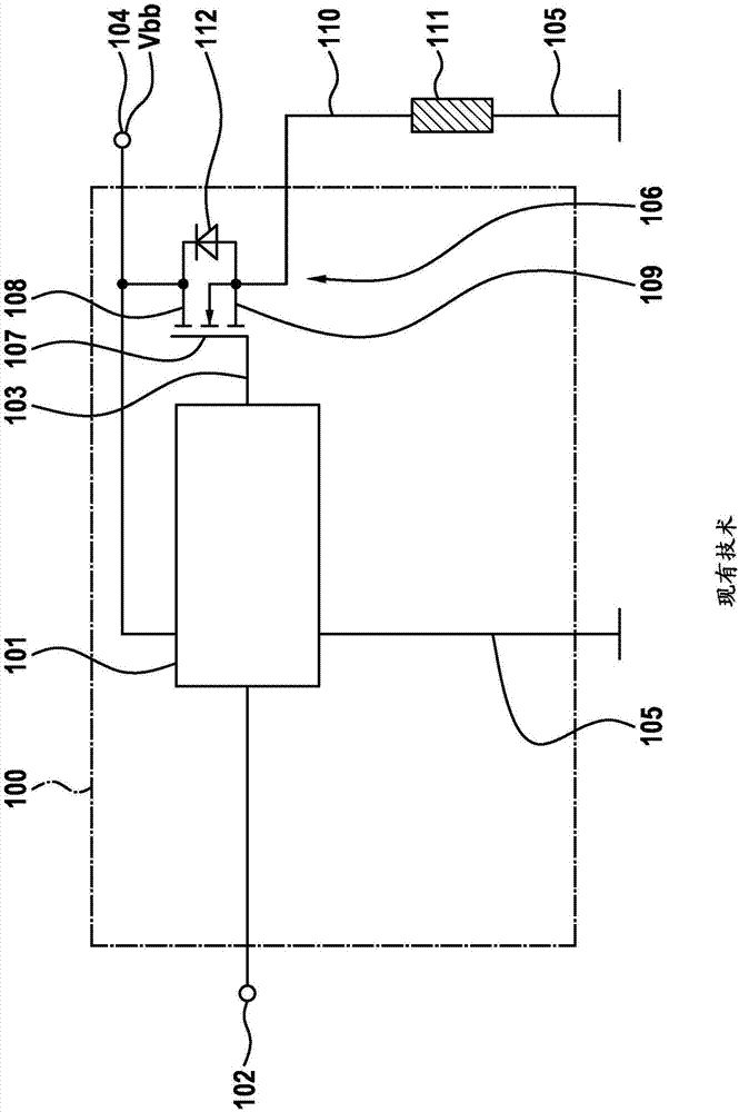
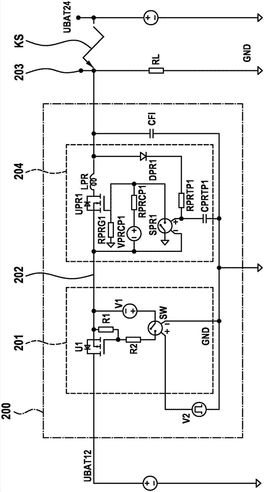
[0023] figure 2 An exemplary embodiment of a protective circuit according to the invention for overvoltage protection of an electronic device 200 embodied as a “high-side switch” 201 is shown. "High-side switch" 201 includes MOSFET U1, which is constructed in the same figure 1 MOSFET 106 consistent. The source-drain-line of MOSFET U1 is arranged between the first operating voltage interface UBAT12 and the device interface 202, said first operating voltage interface provides, for example, a 12-volt power supply from a DC voltage converter or a battery not shown DC voltage. Pulse signal source V2 , which here forms a switch-on signal source, switches MOSFET U1 with control voltage V1 via control position SW and ohmic voltage divider R1 , R2 , so that a switchable voltage can be provided at device interface 202 . A protective circuit 204 according to the invention is arranged between the device interface 202 and the load interface 203 , which connects the load RL to ground GN...


PUM


Abstract

The aim of the invention is to make a device terminal (202; PA_SPK-, PA_SPK+) of an electronic device (200; 300; 400; 410), in particular for a motor vehicle, resistant to short-circuits, even a short-circuit with respect to an offset voltage which exceeds the operating voltage (Vbb), said terminal being designed for an external connection, preferably for connecting to a load (RL). This is achieved by a protective circuit (204; 304; 403; 411) for overvoltage and/or overcurrent protection, comprising a comparison stage (SPR1) for comparing a measurement voltage, which is formed from a voltage applied to the external connection, with a comparison voltage, in particular with a supply voltage or a voltage obtained therefrom of the electronic device (200; 300; 400; 410), and at least one switching element (UPR1, UPR2), which is arranged in series between the device terminal (202; PA_SPK-, PA_SPK+) and the external connection and which can be controlled by the comparison stage (SPR1), for separating the external connection from the device terminal (202; PA_SPK-, PA_SPK+).

Description

Background technique [0001] Electronic devices, in particular entertainment appliances, for use in passenger vehicles are designed for the usual operating voltage of 12 volts therein. In order to be able to supply such devices also in trucks or buses with the on-board electrical system driven there by 24 volts, a DC voltage converter is usually used, via which an additional voltage of 12 volts is provided. If, as usual, the device used in said environment is specified to be short-circuit proof so that said input and output terminals withstand a short circuit to earth and the vehicle battery, this means that at the relevant input and output terminals Fault voltages can arise which are considerably higher than the operating voltage of the device and are thus also significantly higher than the voltage derived from the operating voltage, in particular in the device. This applies in particular when the device is disconnected from its operating voltage (here 12 volts), for example ...

Claims


Application Information

Patent Timeline
Patent Type & Authority Applications(China)
IPC IPC(8): H02H3/087H02H3/20
CPCH02H3/087H02H3/202H02H7/008
Inventor R·默腾布林克
Owner ROBERT BOSCH GMBH
Why Eureka
Try Eureka