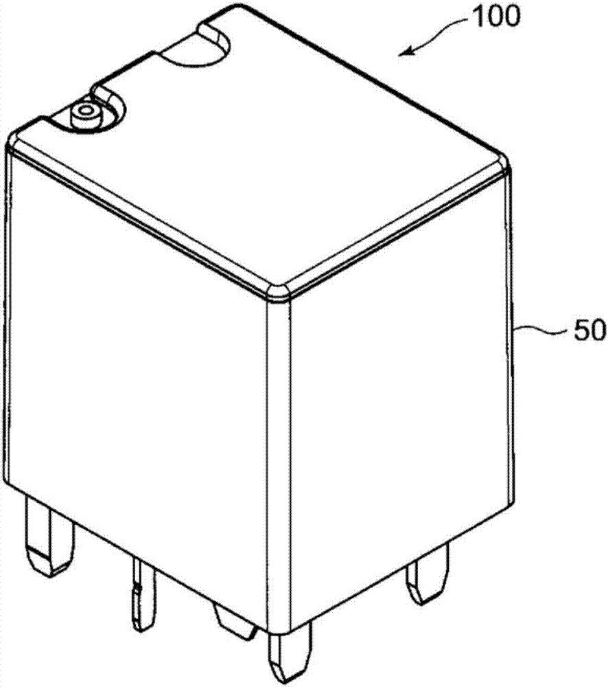
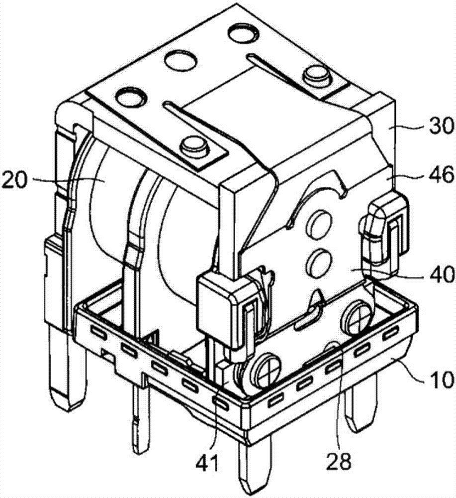
Coil terminal and electromagnetic relay equipped therewith

A technology of coils and terminals, applied in the direction of electromagnetic relays, electromagnetic relay details, relays, etc., can solve the problems of restricting the shape and configuration of coil terminals, difficulty in responding to design changes such as user miniaturization, etc.

Inactive Publication Date: 2017-10-13
ORMON CORP
View PDF7 Cites 0 Cited by
  • Summary
  • Abstract
  • Description
  • Claims
  • Application Information

AI Technical Summary

Problems solved by technology

Therefore, the shape and arrangement of the coil terminals are limited, and it is difficult to respond to design changes such as miniaturization desired by users.

Method used


Image

  • Coil terminal and electromagnetic relay equipped therewith
  • Coil terminal and electromagnetic relay equipped therewith
  • Coil terminal and electromagnetic relay equipped therewith

Examples


other Embodiment approach

[0121] The coil terminal 80 is not limited to the first embodiment. For example, it is also possible to Figure 9 ~ Figure 11 Like the coil terminal 180 of the second embodiment shown, the resistance adjustment portion 187 protrudes in the same direction as the protruding direction of the first to third terminal portions 81 , 82 , and 83 , and the protruding portion is bent together with the connection portion 85 . . By making the resistance adjusting part 187 protrude in the same direction as the protruding direction of the first to third terminal parts 81, 82, 83, for example, when the coil terminal 180 is mounted on the electromagnet device, the resistance adjusting part 187 can be Stored in the free space of the electromagnet unit. Accordingly, it is possible to prevent an increase in the size of the electromagnet device due to the shape of the resistance adjustment portion 187 . In addition, since the connecting portion 85 and the resistance adjusting portion 187 can b...


PUM


Abstract

This coil terminal (80) comprises first to third terminal portions (81, 82, 83) for supplying current to coils (25), a linking portion (84) linking the first to third terminal portions (81, 82, 83), and connecting portions (85) provided on the linking portion (84) and whereto lead wires from the coils (25) are connected. The linking portion (84) is formed from a resistive material, and has a resistance adjustment portion (87) wherein the linking portion (84) is curved at least partially.

Description

technical field [0001] The present invention relates to a coil terminal and an electromagnetic relay provided with the coil terminal. Background technique [0002] Conventionally, as an electromagnetic relay, there is a configuration described in Patent Document 1, for example. This electromagnetic relay includes: an electromagnet device, which has an electromagnet excited by energization and a pair of coil terminals for energizing the electromagnet; And the movable contact contacts or separates. [0003] Patent Document 1: (Japanese) Unexamined Patent Publication No. 2000-11838 [0004] However, in the above-mentioned conventional electromagnetic relay, for example, an existing resistor is provided for absorbing the surge voltage generated by the electromagnet device. Therefore, the shape and arrangement of the coil terminals are limited, and it is difficult to respond to design changes such as miniaturization desired by users. Contents of the invention [0005] The p...

Claims


Application Information

Patent Timeline
Patent Type & Authority Applications(China)
IPC IPC(8): H01H50/14
CPCH01H50/443H01H2050/446
Inventor 佐佐木纯筒井和广
Owner ORMON CORP
Why Eureka
Try Eureka