External descending chamber layout device and measurement method capable of accurately measuring core flow

An accurate measurement, external technology, applied in the direction of measuring fluid flow by measuring pressure difference, volume/mass flow generated by mechanical effects, reactor, etc., can solve the problem that the core flow cannot be accurately measured, and achieve the effect of improving safety

Active Publication Date: 2017-12-12
NUCLEAR POWER INSTITUTE OF CHINA
View PDF5 Cites 0 Cited by
  • Summary
  • Abstract
  • Description
  • Claims
  • Application Information

AI Technical Summary

Problems solved by technology

[0004] The purpose of the present invention is to provide an external descending chamber layout device that can accurately measure the core flow, and solve the problem that the core flow of the existing reactor simulation body cannot be accurately measured

Method used


Image

  • External descending chamber layout device and measurement method capable of accurately measuring core flow
  • External descending chamber layout device and measurement method capable of accurately measuring core flow
  • External descending chamber layout device and measurement method capable of accurately measuring core flow

Examples


Embodiment 1

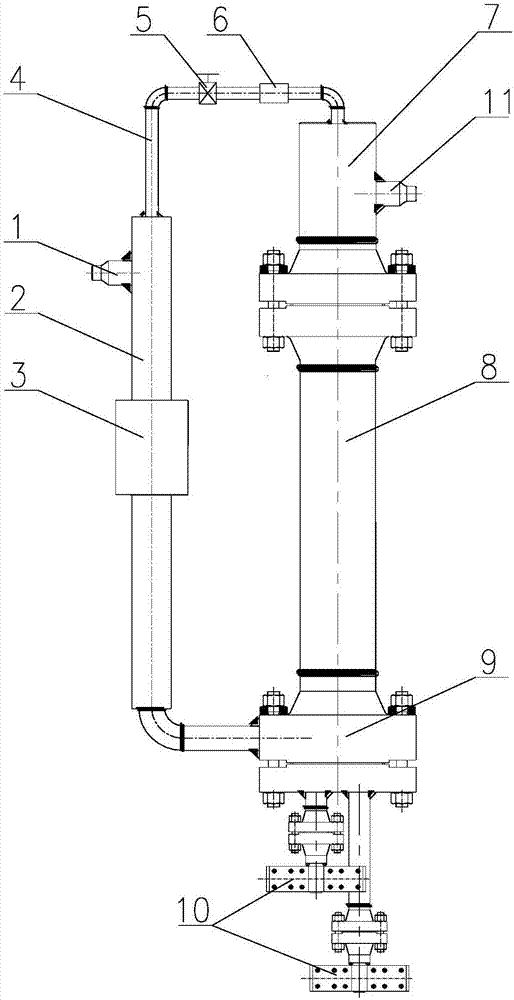
[0058] Such as figure 1 As shown, the external descending chamber layout device that can accurately measure the core flow rate includes a core simulation section 8, the lower end of which is communicated with the descending section pipeline 2 through a lower flange 9, and the descending section The bottom end of the pipeline 2 is welded with the perforated lower flange 9 through an elbow, the lower end of the lower flange 9 is provided with a power supply copper bar 10, and the descending section pipeline 2 is provided with a first flow meter 3, The upper end of the core simulation section 8 communicates with the upper head 7 through the upper flange, the upper side of the descending section pipeline 2 is welded with an inlet pipe 1, and the side of the upper head 7 is welded with an outlet pipe 11. Including a bypass pipeline 4, one end of the bypass pipeline 4 communicates with the descending pipeline 2, preferably, the flow pipeline 4 is welded with the descending pipeline ...

Embodiment 2

[0061] Such as figure 1 As shown, this embodiment is based on Embodiment 1, the bypass pipeline 4 is provided with an orifice 5 , and the diameter of the orifice 5 is adjustable.

[0062] Experimental process of this embodiment: By adjusting the resistance of the orifice 5 , the simulation of bypass flow under different working conditions can be realized.

Embodiment 3

[0064] This embodiment is based on Embodiment 1 or Embodiment 2, and the diameter of the bypass pipeline 4 is 1 / 4 of the diameter of the pipeline 2 in the descending section.

[0065] A method for measuring flow based on the external descending chamber arrangement device described in Embodiment 2, comprising the following steps:

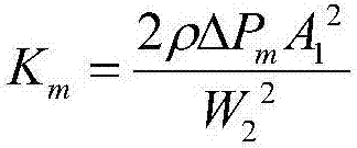
[0066] 1) Adjust the resistance of the bypass pipeline: adjust the hole diameter of the orifice plate 5 on the bypass pipeline 4 to make the pressure drop Δp of the bypass pipeline 4 under the reference working condition m and design value Δp s The deviation is within ±5%;

[0067] 2), measurement of flow rate: the flow rate W flowing through the simulation section 8 of the core is measured by the first flowmeter 3 1 , the flow rate W of the bypass pipeline 4 is measured by the second flowmeter 6 2 .

[0068] Specific steps for adjusting the resistance of the bypass pipeline 4 through the orifice 5:

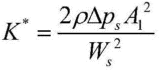
[0069] 1) Determine the resistance coefficie...


PUM


Abstract

The invention discloses an external descending chamber layout device and a measurement method capable of accurately measuring core flow. The external descending chamber layout device includes a core simulation section, and the lower end of the core simulation section passes through the lower flange and the descending section. The pipes in the descending section are connected with a first flowmeter, the upper end of the core simulation section communicates with the upper head through the upper flange, the inlet pipe is arranged on the pipes in the descending section, and the upper end of the upper head An outlet pipeline is arranged on the top, and a bypass pipeline is also included. One end of the bypass pipeline communicates with the pipeline of the descending section, and the other end communicates with the upper head. A second flowmeter is arranged on the bypass pipeline. The present invention completely simulates the fluid pipeline of the actual reactor by setting the descending section pipeline and the side flow pipeline matched with the reactor core simulation section, and respectively measures the flow rates flowing through the downgoing section pipeline and the bypass flow pipeline, avoiding There is an inaccurate measurement caused by the simulation body ignoring the bypass pipeline.

Description

technical field [0001] The invention relates to the technical field of flow measurement of nuclear reactors, in particular to an external descending cavity arrangement device and a measurement method capable of accurately measuring core flow. Background technique [0002] The reactor simulation body is the core equipment for conducting out-of-reactor simulation experiments, and the thermal and hydraulic characteristics of the reactor simulation body are of great significance to the safe operation of the reactor. Usually, when calculating the thermal-hydraulic characteristics of the reactor simulation body, it is considered that all the fluid flows through the core, but in fact, in order to ensure the inherent safety of the reactor, there is often a bypass flow in the design of the reactor, and the bypass fluid is directly heated without heating the core. out of the reactor. Due to the existence of bypass flow, the thermal-hydraulic characteristics experiments and correspond...

Claims


Application Information

Patent Timeline
Patent Type & Authority Patents(China)
IPC IPC(8): G21C17/00G01F1/34
CPCG01F1/34G21C17/001Y02E30/30
Inventor 谢添舟陈炳德黄彦平徐建军唐瑜周慧辉
Owner NUCLEAR POWER INSTITUTE OF CHINA
Why Eureka
Try Eureka