
Gimbals, Unmanned Aerial Vehicles, Filming Equipment, and Movable Equipment

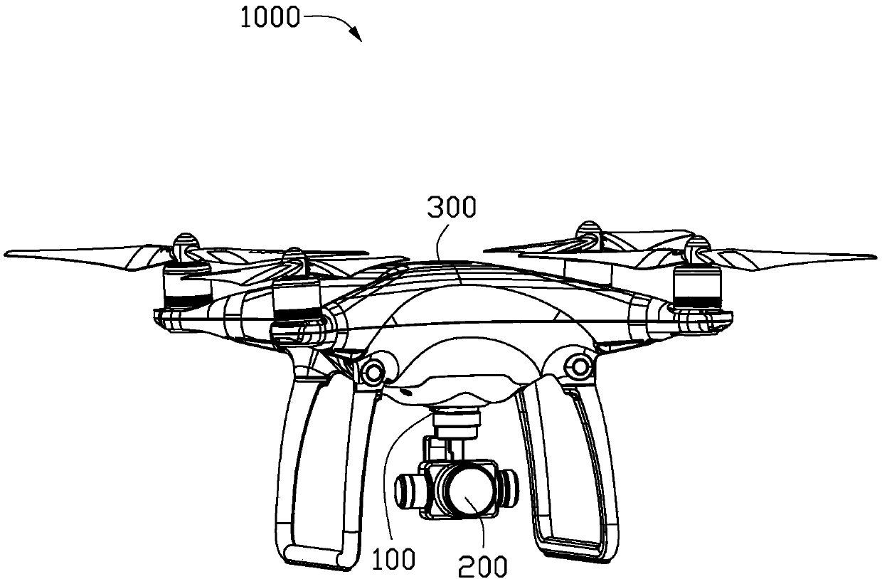
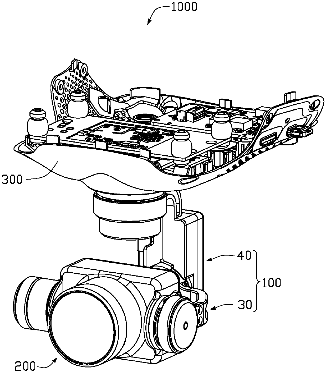
A technology for unmanned aerial vehicles and gimbals, which is applied in the fields of unmanned aerial vehicles, gimbals, shooting equipment and mobile devices, and can solve problems such as unbalanced gimbal center of gravity, unfavorable gimbal load control, and easy shaking

Active Publication Date: 2019-04-19
SZ DJI OSMO TECH CO LTD
View PDF5 Cites 0 Cited by
  • Summary
  • Abstract
  • Description
  • Claims
  • Application Information

AI Technical Summary

Problems solved by technology

This will cause the end where the motor and control wires are located to be heavy, and it will take up a lot of space
When the unmanned aerial vehicle equipped with the gimbal accelerates or decelerates in different directions, the gimbal tends to shake due to the unbalanced center of gravity, which is not conducive to the control of the gimbal and the load mounted on the gimbal

Method used


Image

  • Gimbals, Unmanned Aerial Vehicles, Filming Equipment, and Movable Equipment
  • Gimbals, Unmanned Aerial Vehicles, Filming Equipment, and Movable Equipment
  • Gimbals, Unmanned Aerial Vehicles, Filming Equipment, and Movable Equipment

Examples


Embodiment Construction

[0176]It should be noted that when a component is said to be "fixed" to another component, it can be directly on the other component or there can also be an intervening component. When a component is said to be "connected" to another component, it may be directly connected to the other component or there may be intervening components at the same time. The terms "vertical," "horizontal," "left," "right," and similar expressions are used herein for purposes of illustration only.

[0177] Unless otherwise defined, all technical and scientific terms used herein have the same meaning as commonly understood by one of ordinary skill in the technical field of the invention. The terms used herein in the description of the present invention are for the purpose of describing specific embodiments only, and are not intended to limit the present invention. As used herein, the term "and / or" includes any and all combinations of one or more of the associated listed items.

[0178] The follow...


PUM


Abstract

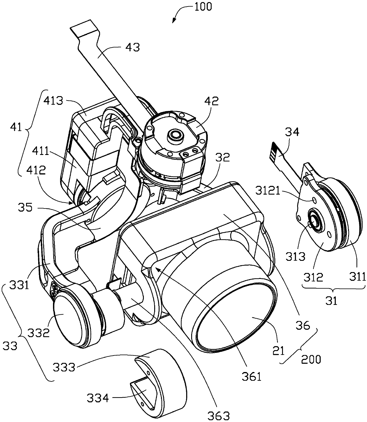
A cloud platform (100) and an unmanned aerial vehicle (1000) using the platform (100), a photographing device and a movable device. The cloud platform (100) includes a body (40) and a first bracket component (30) arranged on the body (40). The first support assembly (30) includes a first support arm (32) and a second support arm (33) respectively extending from the body (40) and capable of rotating relative to the body (40). The support arm (32) is arranged opposite to the end of the second support arm (33), and can rotatably sandwich a load (200) therebetween. The first bracket assembly (30) also includes a first driving device (31), which is arranged on the end of the first support arm (32) away from the body (40), and is used to drive the load (200) relative to the The first bracket assembly (30) is rotated. The platform (100) further includes a first signal transmission member (35), extending along the second support arm (33) and capable of being electrically connected to the load (200).

Description

technical field [0001] The invention relates to a connection structure of an airborne platform, in particular to a platform, an unmanned aerial vehicle, a photographing device and a movable device. Background technique [0002] In existing gimbal designs, most airborne gimbals use a single-arm support structure, especially the design of the pitch (Pitch) axis. In the design of the large pan / tilt, although there is a double-arm support structure, the pan / tilt control motor and the control line are usually placed at the same end. This will cause the end where the motor and control wires are located to be heavy and occupy a large space. When the unmanned aerial vehicle equipped with the gimbal accelerates or decelerates in different directions, the gimbal tends to shake due to the unbalanced center of gravity, which is not conducive to the control of the gimbal and the load mounted on the gimbal. Contents of the invention [0003] In view of this, it is necessary to propose...

Claims


Application Information

Patent Timeline
IPC IPC(8): G03B17/56
CPCG03B17/56
Inventor 陈子寒潘大虎
Owner SZ DJI OSMO TECH CO LTD
Learn More