
LED (light emitting diode) screen splicing structure and LED screen

A technology of LED screen and spring connection, applied in the direction of connecting components, thin plate connection, identification device, etc., can solve the problems of insufficient applicability, many adjustable angles, short service life, etc., and achieve simple and uncomplicated mechanism and easy angle adjustment , The effect that disassembly is not easy

Active Publication Date: 2017-10-13
LKK DESIGN SHENZHEN
View PDF12 Cites 11 Cited by
  • Summary
  • Abstract
  • Description
  • Claims
  • Application Information

AI Technical Summary

Problems solved by technology

But at present, many connection devices are fixed connections, and the angle between the light boxes cannot be adjusted, which cannot meet the diverse needs of the market.
Although, there are some angle-adjustable adjusting devices in the prior art as the publication number is (the patent document of CN102858125A), this adjusting device is installed between two display screen cabinets, can adjust two adjacent display screen cabinets as required According to different use requirements, the angle between the two display cabinets can be adjusted to different angles, but its applicability is not enough; 1. Due to the many adjustable angles, there are many parts and mechanisms There will also be a large number of assembly tolerances on the surface, which will loosen due to frequent disassembly and assembly, resulting in safety hazards
2. The adjustment angle is not smooth, easy to get stuck
3. Angle adjusters on the market have a short service life and are easily damaged

Method used


Image

  • LED (light emitting diode) screen splicing structure and LED screen
  • LED (light emitting diode) screen splicing structure and LED screen
  • LED (light emitting diode) screen splicing structure and LED screen

Examples


Embodiment Construction

[0035] In order to make the technical problems solved by the present invention, the technical solutions adopted and the technical effects achieved clearer, the technical solutions of the embodiments of the present invention will be further described in detail below in conjunction with the accompanying drawings. Obviously, the described embodiments are only the technical solutions of the present invention. Some, but not all, embodiments. Based on the embodiments of the present invention, all other embodiments obtained by those skilled in the art without creative efforts fall within the protection scope of the present invention.

[0036] In the description of the present invention, unless otherwise clearly specified and limited, the terms "connected", "connected" and "fixed" should be understood in a broad sense, for example, it can be a fixed connection, a detachable connection, or an integrated ; It can be a mechanical connection or an electrical connection; it can be a direct...


PUM


Abstract

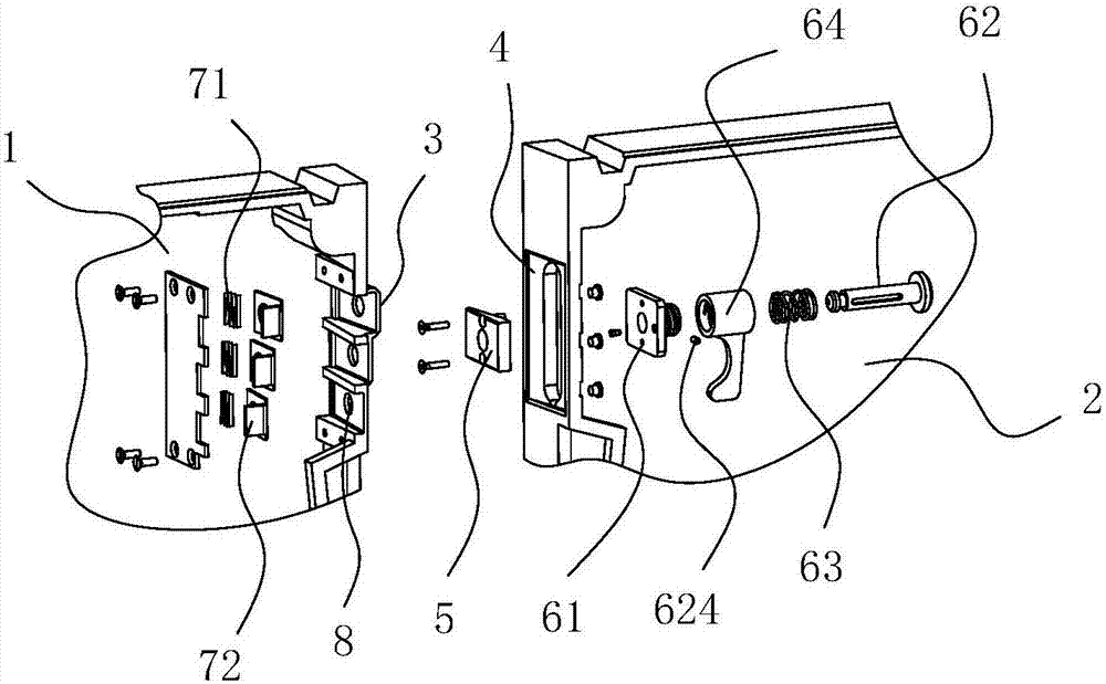
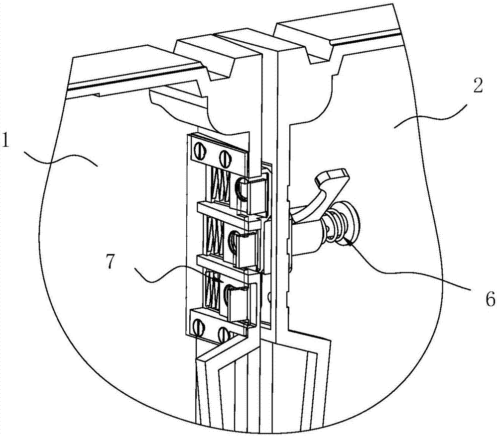
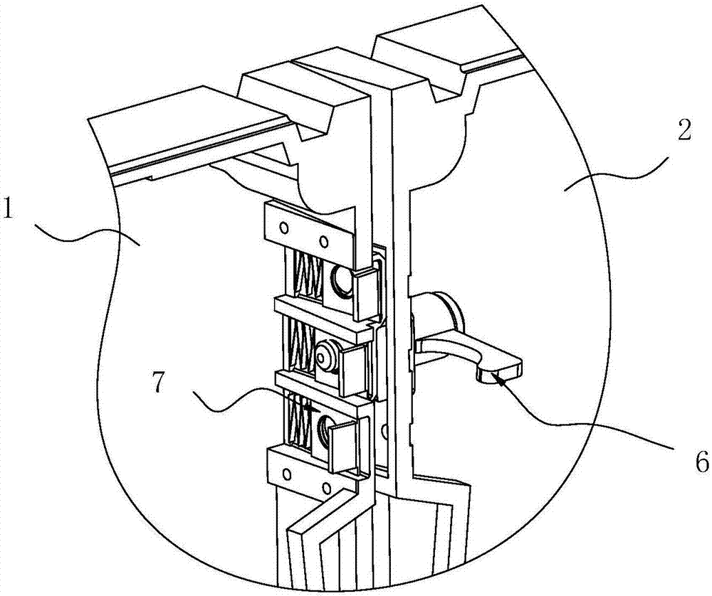
The invention discloses an LED (light emitting diode) screen splicing structure and an LED screen. The LED screen splicing structure comprises a first box and a second box, the first box and the second box are spliced mutually, the first box comprises a first side wall facing the second box, the second box comprises a second side wall opposite to the first side wall, the first side wall is provided with a plurality of limiting faces in different angles, the second side wall is provided with a slide groove corresponding to position of the limiting faces, and a wedged slider is movably arranged in the slide groove. The first box and the second box are fixedly connected through a spring connector penetrating the wedged slider, and an included angle between the first box and the second box is defined by the wedged slider and the limiting faces jointly. Angle nonuniformity in splicing is realized by matching of the wedged slider and the limiting faces, assembly and fastening of the two boxes are realized by the aid of a spring connection lock, and easiness in angle adjustment, mechanism simplicity, steadiness in connection for use, less proneness to loosing in repeated disassembly, part design and cost reduction, easiness in processing and accordance with market requirements are realized.

Description

technical field [0001] The invention relates to the technical field of splicing electronic equipment, in particular to an LED screen splicing structure and an LED screen using the splicing structure. Background technique [0002] LED display screen is a new type of flat-panel display device that appeared in the 1990s. Due to its clear picture, high brightness, and bright colors, it has gradually become the only one in the field of public multimedia display. LED displays are also widely used, such as light box advertisements, outdoor billboards, indoor screen displays, etc. However, in the case of some large display screens composed of multiple smaller display screens, it is usually necessary to use a connecting device to assemble multiple display screen modules together. However, at present, many connection devices are fixed connections, and the angle between the light boxes cannot be adjusted, which cannot meet the diverse needs of the market. Although, there are some ang...

Claims


Application Information

Patent Timeline
Patent Type & Authority Applications(China)
IPC IPC(8): G09F9/33F16B5/00F16B21/18
CPCG09F9/33F16B5/0024F16B5/0088F16B21/18
Inventor 张健辉谭伟创蔡高佳李湘驰
Owner LKK DESIGN SHENZHEN
Learn More